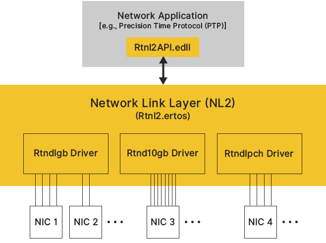
The Network Link Layer (NL2) software component provides real-time applications with abstract APIs to access network services at the Layer 2 of the OSI model, independent of the underlying hardware. The image below shows a high-level layout of the NL2 architecture.
Interactions with Real-Time Applications
The diagram below focuses on the interactions between the NL2 and real-time applications:
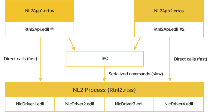
In this example, 3 eRTOS processes are running:
- The NL2 (Rtnl2.ertos), which has loaded 4 different NIC Drivers (NicDriver1.edll, NicDriver2.edll, NicDriver3.edll, NicDriver4.edll).
- Two NL2 Application (NL2App1.ertos and NL2App2.ertos). Each of them has loaded its copy of Rtnl2Api.edll and communicates with the NL2 through 2 different paths:
- A “slow” path is used for everything that doesn’t require real-time performance. Requests from multiple applications using this path are serialized.
- A “fast” path from Rtnl2Api.edll into rtNL2.ertos is used for packet transmission and reception functions that require real-time performance with no context switching.
NL2 Objects and Concepts
Network Interfaces (NICs)
A Network Interface, or simply an Interface, is a component connected to a network. It allows an application to send and receive Ethernet frames to/from the connected network.
An Interface may have one or more Hardware Receive Queues and one or more Hardware Transmit Queues.
Note: Network Interfaces are also called NICs (Network Interface Cards). The term NIC is sometimes preferable as it avoids confusion between network interfaces and software programming interfaces.
Hardware Receive Queues
A Hardware Receive Queue is a hard-wired sub-component of a NIC. It represents an entry point for receiving Ethernet packets through the NIC.
Each Hardware Receive Queue has its FIFO of received frames. The advantages of multiple Hardware Receive Queues are:
- Allow multiple applications (typically running on multiple cores) to simultaneously receive frames through the same NIC; dispatching received frames is handled at the hardware level.
- Avoid interferences between multiple classes of traffic.
Hardware Transmit Queues
A Hardware Transmit Queue is a hard-wired sub-component of a NIC. It represents an entry point for transmitting Ethernet packets through the interface.
Each Hardware Transmit Queue has its FIFO of frames ready to be transmitted. The advantages of multiple Hardware Transmit Queues are:
- Allow multiple applications (typically running on multiple cores) to simultaneously send frames through the same NIC; the multiplexing of transmitted frames is handled at the hardware level.
- Manage QoS between multiple traffic classes.
Physical Receive Queues
A Physical Receive Queue is the representation in the NL2 of a Hardware Receive Queue.
NL2 Physical Receive Queue objects allow real-time applications to get exclusive, low-latency access to a NIC's Hardware Receive Queues.
Physical Transmit Queues
A Physical Transmit Queue is the representation in the NL2 of a Hardware Transmit Queue.
NL2 Physical Transmit Queue objects allow real-time applications exclusive low-latency access to a NIC's Hardware Transmit Queues.
Buffers
A Buffer is a memory block that contains one Ethernet packet (either a packet ready to be transmitted or a received packet) and is accessible both by the CPU and the NIC (through DMA).
Buffers are normally managed internally by the NL2 and the driver, except when the application uses the Physical Queue interface (see below), in which case the application has direct access to them.
Logical Receive Queues
A Logical Receive Queue is a software sub-component of a NIC that allows multiple applications to access the same Hardware Receive Queue simultaneously.
Logical Receive Queues provide real-time applications with the same services as Physical Receive Queues but don’t achieve the same latency performance.
Logical Transmit Queues
A Logical Transmit Queue is a software sub-component of a NIC that allows multiple applications to access the same Hardware Transmit Queue simultaneously.
Logical Transmit Queues provide real-time applications with the same services as Physical Transmit Queues but don’t achieve the same latency performance.
Reception Model
The diagram below shows the path followed by Ethernet packets in a NIC, from their reception from the wire to their consumption in the applications. Gray objects represent hardware components and data belonging to the NIC, while red objects represent the software components and data belonging to the NL2.
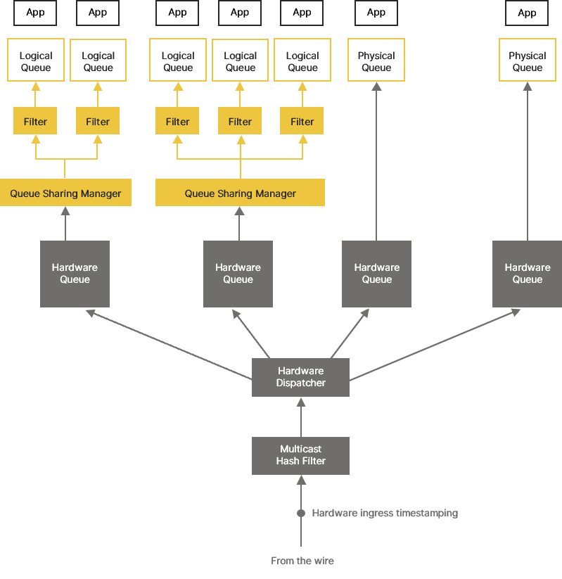
A given NIC may have one or more Hardware Receive Queues. Their number is fixed and hardware dependent.
When an Ethernet frame arrives from the wire, it first passes through a Hardware Multicast Hash Filter, eliminating undesired multicast frames as early as possible.
Next, the frame goes through the Hardware Dispatcher, which determines the appropriate Hardware Receive Queue to which the frame must go. The algorithm uses a set of rules based on the frame's EtherType, UDP Port, PCP value, etc. If no rule matches the incoming frame, it is forwarded to the Default Hardware Receive Queue, which is always the first Hardware Receive Queue.
The NL2 provides two programming interfaces to access the Hardware Receive Queues:
- The Logical Queue interface allows multiple applications to share the same Hardware Receive Queue through a logical queue abstraction.
- The Physical Queue interface provides greater control over the hardware but doesn’t allow queue sharing.
The same application may simultaneously use multiple Hardware Receive Queues, which can belong to the same NIC or different NICs.
With the Logical Queue interface, each application using a given Hardware Receive Queue has its own Logical Receive Queue. A Logical Receive Queue consists of a list of local buffers maintained by the NL2 and organized as a queue. Each Logical Receive Queue has a specified size (i.e., the maximum number of received buffers in the queue simultaneously), which is determined and fixed upon creation.
Every frame received by the underlying Hardware Receive Queue is copied to a local buffer of each Logical Receive Queue that claims interest in that frame (based on the execution of Logical Filters). Later, when the application requests the reception of the next frame, the content of the next local buffer is copied to the application buffer.
The Logical Filters associated with a Logical Receive Queue evaluate each received frame against the following parameters:
- The EtherType
- The Destination MAC Address
With the Physical Queue interface, a given Hardware Receive Queue can only be used by one application at a time. In this case, the NL2 does not provide logical queue management. The NL2 allocates the Buffers associated with a given Hardware Receive Queue at startup. The hardware fills these Buffers with the contents of incoming Ethernet frames. Buffers containing Ethernet frame content are transferred to the application for consumption, then the application returns the Buffer to the Hardware Receive Queue for re-use for another incoming Ethernet frame. Unlike the Logical Queue interface, Physical Queue interface doesn’t copy user data. The hardware directly fills Buffers, and then a reference to them is given to the application.
When using the Physical Queue interface, the application can enable or disable the Receive Interrupt associated with the Hardware Receive Queue, improving performance in some situations.
Transmission model
The diagram below shows the path followed by Ethernet packets in a NIC, from their production in the applications to their transmission onto the wire. Red objects represent the software components and data belonging to the NL2, while gray objects represent hardware components and data belonging to the NIC.
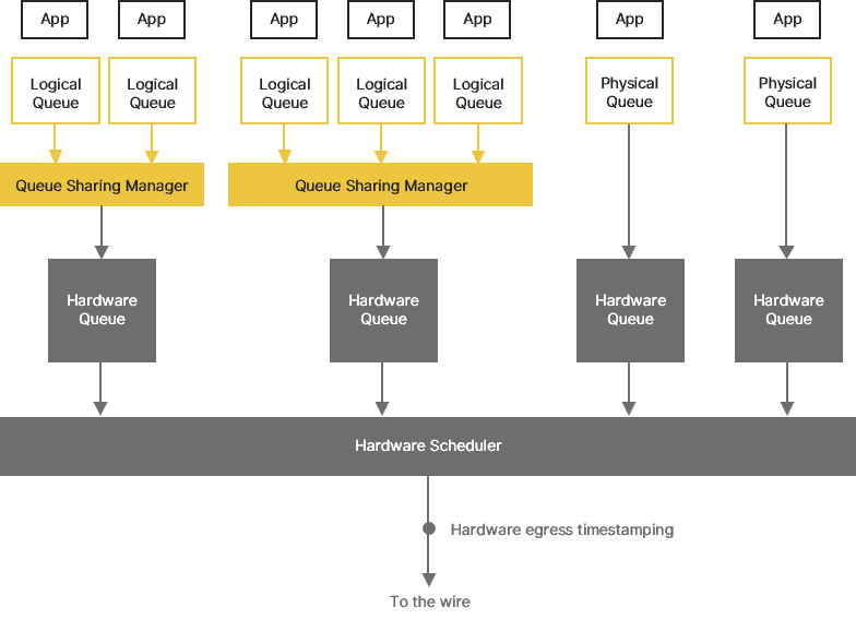
A given NIC may have one or more Hardware Transmit Queues. Their number is fixed and hardware-dependent.
The NL2 provides two programming interfaces to access the Hardware Transmit Queues:
- The Logical Queue interface allows multiple applications to share the same Hardware Transmit Queue through a logical queue abstraction.
- The Physical Queue interface provides greater control over the hardware but doesn’t allow queue sharing.
The same application may use multiple Hardware Transmit Queues simultaneously, belonging to the same NIC or different NICs.
With the Logical Queue interface, each application using a given Hardware Transmit Queue has its own Logical Transmit Queue. A Logical Transmit Queue consists of a list of local buffers maintained by the NL2 and organized as a queue. Each Logical Transmit Queue has a specified size (i.e., the maximum number of transmit buffers in the queue simultaneously), which is determined and fixed upon creation.
When an application requests transmission, user data is directly copied into a Buffer of the Hardware Transmit Queue if one is available. Otherwise, user data is copied to a local buffer of the Logical Transmit Queue, and copied again to a Buffer of the Hardware Transmit Queue when one becomes available. Buffers become available as soon as the NIC consumes their content.
With the Physical Queue interface, a given Hardware Transmit Queue can only be used by one application at a time. In this case, the NL2 doesn't provide logical queue management. The application requests Buffers, fills them in, inserts them in the Hardware Transmit Queue, and retrieves them once the hardware has fully consumed their content. Unlike the Logical Queue interface, the Physical Queue interface doesn’t copy user data. Buffers are directly filled by the application and then referenced by the hardware.
When using the Physical Queue interface, the application can enable or disable the Transmit Interrupt associated with the Hardware Transmit Queue, improving performance in some situations.