In this section, we introduce the Network Link Layer (NL2) and explain how to create an application that uses the NL2.
Topics:
- Creating a Project
- Using the Samples
- Implementing the Application
- Automatic Cleanup after an Attached Application Terminates
- Memory Allocated by the NL2
- Shutdown Handling
Creating a Project
To create a project in Visual Studio:
- Create a new project in Visual Studio.
- Select C or C++ as the template type.
- Select the wRTOS RTSS Application Template.
- Select Network Link Layer Support.
- Select Finish to create the project.
Using the Samples
wRTOS SDK provides source code and project files for NL2 application samples. You can use these samples as a reference when implementing your application.
Implementing the Application
Attaching an RTSS Process to the NL2
Before using the functionality of the NL2, an application must call Rtnl2Init.
Note: Ensure the NL2 component is started before calling Rtnl2Init, or the call will fail. See Controlling the NL2 Programmatically for more details.
This call attaches the application to the NL2. After a call to Rtnl2Init, all the threads of the calling process are allowed to call the other API functions of the NL2.
Note: There is no such function as Rtnl2End. After a successful call to Rtnl2Init, the process remains attached to the NL2 until it terminates. See Automatic Cleanup after an Attached Application Terminates.
Enumerating Interfaces
At startup, the NL2 builds a list of all the network interfaces it manages, which is not modified afterwards. Each interface is assigned an index at startup and this index doesn’t change over the life of the NL2.
The Rtnl2EnumInterface function allows the application to retrieve the name of an Interface specified by its index.
To get the list of all available Interfaces, the application can call Rtnl2EnumInterface in a loop, starting with an index of 0 and incrementing until the function fails with the ERROR_NO_MORE_ITEMS error code.
Note: The index value associated with an interface is arbitrary and doesn’t represent any meaningful information about the interface.
Opening an Interface
Before being able to manipulate an interface, the application must open a handle to it. This is done by calling the Rtnl2OpenInterface function.
This function takes the interface name as a parameter and returns a handle.
Once the application no longer needs the interface handle, it must close it by calling Rtnl2CloseInterface. A handle to an interface can't be closed when a Link Status Change event is associated with that handle (see Query and Monitor the Link Status).
Getting the MAC Address of an Interface
An application can retrieve the MAC Address of an interface at any time by calling the Rtnl2GetMacAddress function.
Getting the Supported Features of an Interface
The NL2 populates an RTNL2_INTERFACE_FEATURES structure for each interface, containing the list of features supported by that interface.
An application can retrieve the content of this structure at any time by calling the Rtnl2GetInterfaceFeatures function.
Getting the Configuration of the Interfaces, the MSI-X Messages, and the Queues
The NL2 reads its static configuration (created in wRTOS Settings) and applies it at startup.
It also populates the following data structures for each interface with the applied configuration:
- An RTNL2_INTERFACE_CONFIG structure that contains the interface configuration.
- An RTNL2_MSIX_MESSAGE_CONFIG structure that contains the configuration of each enabled MSI-X Message.
- An RTNL2_PHYSICAL_RX_QUEUE_CONFIG structure that contains each enabled Physical Receive Queue configuration.
- An RTNL2_PHYSICAL_TX_QUEUE_CONFIG structure that contains each enabled Physical Transmit Queue configuration.
The application can retrieve the contents of all these data structures at any time by calling Rtnl2GetInterfaceConfig, Rtnl2GetMsixMessageConfig, Rtnl2GetPhysicalRxQueueConfig, and Rtnl2GetPhysicalTxQueueConfig.
Querying and Monitoring the Link Status
The Rtnl2GetLinkStatus function can be called at any time to retrieve the current link status of an interface.
In addition, an application can request the creation of an Event object signaled by the NL2 whenever the link status of a specific interface changes. This is done by calling Rtnl2CreateLinkStatusChangeEvent, which returns a handle to the created event. The application can then use it in subsequent calls to RtWaitForSingleObject or RtWaitForMultipleObjects.
When the application no longer needs to monitor an interface's link status, it must destroy the Link Status Change event by calling Rtnl2DestroyLinkStatusChangeEvent.
Manipulating the Hardware Clock of an Interface
Overview
Interfaces that support hardware timestamping have one or several onboard local clock(s) whose counter gets incremented on a periodic basis. Depending on the hardware, several operations may be possible on those onboard hardware clocks:
- Read the current clock counter value and cross-timestamp it with the CPU clock
- Adjust the clock time by applying an offset to the current counter value
- Set/Get the clock rate
Cross-timestamping can be done in software or in hardware.
Software cross-timestamping involves reading the NIC time and the CPU time within a very short interval (a few microseconds). Hardware timestamping with PTM (Precision Time Measurement) consists of letting the hardware read the two clocks simultaneously. This provides more accurate results (in the order of nanoseconds).
Opening and Closing a Handle to a Hardware Clock
Before any of the above operations can be performed on a given Hardware Clock, the application must open a handle to it by calling Rtnl2OpenClock.
If the application plans to modify the hardware clock, it must set the appropriate flag when calling the Rtnl2OpenClock function. This allows the NL2 to ensure only one handle at a time has been opened with modification rights.
The application can also specify at open time whether it wants to perform cross-timestamping operations in software or in hardware (using PTM). See RTNL2_INTERFACE_FEATURES.PtmEnabled to determine whether PTM is available for use on the interface.
When the application no longer needs to manipulate the Hardware Clock, it must close the handle by calling Rtnl2CloseClock.
Reading the Current Time of a Hardware Clock and Cross-timestamping it with the CPU Clock
If the hardware allows it, the application can read the current time of a hardware clock by calling Rtnl2ReadClock. See RTNL2_INTERFACE_FEATURES.ReadClockSupported to determine whether this operation is supported by your hardware.
Although the hardware clock counter may have a nominal frequency lower than 1Ghz, the NL2 ensures that the hardware counter gets converted to a few seconds and nanoseconds before it returns it in an RTNL2_TIMESTAMP structure.
In addition to reading the NIC clock time, this function also reads the CPU clock time. All the timestamps, as well as other information about the performed operation, are returned in a RTNL2_READ_CLOCK_RESULT structure.
If the clock handle was opened with the PTM flag, the NL2 first attempts the cross-timestamping operation in hardware, using PTM. If this fails, it uses the software method. If the handle to the clock was opened without that flag, the NL2 uses the software method. At the end of the operation, the NL2 populates the RTNL2_READ_CLOCK_RESULT.Flags field to indicate the method used.
The NL2 also indicates in the RTNL2_READ_CLOCK_RESULT.Flags field whether the clock has been modified by another handle since the last time it was read. This allows the application to reinitialize its smoothing algorithm in case the modification was done asynchronously by another application.
Adjusting the Time of a Hardware Clock
If the hardware allows it, the application can adjust the current time of a hardware clock by applying an offset to the current time. This is done by calling Rtnl2AdjustClockTime. See RTNL2_INTERFACE_FEATURES.AdjustClockTimeSupported to determine whether this operation is supported by your hardware.
Depending on the hardware capabilities, the NL2 will use one of the two following methods:
- Method 1 (preferred, if available): provide the offset directly to the hardware and let the hardware apply the offset. This is a very precise method, but it generally works with small offset values only. See RTNL2_INTERFACE_FEATURES.ClockTimeFineOffsetMax and RTNL2_INTERFACE_FEATURES.ClockTimeFineOffsetMin.
- Method 2: read the current counter value, add the offset to it, and write the new counter value. This method is much less precise because reading and writing hardware registers takes a non-negligible and variable amount of time.
Attention:
- Modifying the clock time is a disruptive operation that should be done with the greatest care. Whenever possible, it is preferable to maintain a logical time offset in software rather than modifying the hardware clock time.
- If this clock is currently used by another application (typically PTP for Ethernet packet ingress/egress timestamping), that other application should be made aware of the modification by some means outside of the NL2. Otherwise, it may wrongly interpret invalid timestamps and behave incorrectly.
- Hardware clocks generally use a hardware register to record the value of their counter (e.g. a 32-bit register for the number of seconds, and another 32-bit register for the number of nanoseconds, or a single 64-bit register for the number of seconds). The size of this(these) register(s) is normally sufficient to avoid counter overflow for a very long time (e.g. 136 years for a 32-bit seconds register). However, if the application modifies the clock time by applying a large offset, it may cause the counter to overflow, resulting in the clock time wrapping around. The NL2 does not prevent this. It’s the application’s responsibility to ensure it doesn’t happen, or to handle it correctly if it does. A similar problem occurs when applying a large negative time offset (counter underflow). See RTNL2_INTERFACE_FEATURES.ClockTimeRange to determine the range of possible values for the hardware clock time.
Adjusting the Rate of a Hardware Clock
If the hardware allows it, the application can modify the actual rate of the clock (inverse of the time that elapses between two increments of the clock counter), by calling Rtnl2SetClockRate. See RTNL2_INTERFACE_FEATURES.SetClockRateSupported to determine whether this operation is supported by your hardware.
The Rtnl2GetClockRate function returns the actual clock rate.
The actual clock rate is expressed relative to the nominal clock rate, in ppm. The RTNL2_INTERFACE_FEATURES.ClockRateScaledOffsetPpmMax and RTNL2_INTERFACE_FEATURES.ClockRateScaledOffsetPpmMin fields indicate the range of values supported by the hardware. If an out-of-range value is supplied, the NL2 will clamp it to the nearest supported value.
If you need to adjust the clock rate relative to the current rate instead of the nominal rate, read the current rate with Rtnl2GetClockRate, add your adjustment to it, and then call Rtnl2SetClockRate with the new value.
Control Special Functions of a Device
Some hardware may have special functions that are not exposed by the NL2 API due to various reasons, including:
- The function is hardware-specific and cannot be abstracted in a generic way.
- The function is made for debug purposes only.
- The function is not supported by the NL2.
To allow custom drivers to expose special functions to the application, the NL2 provides the function Rtnl2ControlDeviceSpecialFunction. This API passes the supplied arguments to the underlying driver without interpreting them.
Configuring the Hardware Dispatcher
The Hardware Dispatcher decides which Physical Receive Queue each frame received from the wire must go to. At startup, the default behavior of the Hardware Dispatcher is to forward all received frames to the same Physical Receive Queue, which is queue 0 (also known as the Default Receive Queue).
Actual Hardware Dispatchers can generally forward received frames based on various criteria, such as their EtherType, PCP (Priority Code Point), and UDP destination port. Hardware Dispatcher's configuration consists of a set of Dispatch rules that can be dynamically added and removed on demand.
The number of EtherType dispatch rules supported by a given interface is reported in the EtherTypeDispatchRulesCount field of the RTNL2_INTERFACE_FEATURES structure, which can be retrieved by calling Rtnl2GetInterfaceFeatures. A value of 0 for the EtherTypeDispatchRulesCount field indicates that the Hardware Dispatcher of this interface doesn't support EtherType dispatch rules. Similarly, the number of PCP dispatch rules supported by a given interface is reported in the PcpDispatchRulesCount field of the RTNL2_INTERFACE_FEATURES structure. Finally, the number of UDP Port dispatch rules supported by a given interface is reported in the UdpPortDispatchRulesCount field of the RTNL2_INTERFACE_FEATURES structure.
To add an EtherType dispatch rule, call Rtnl2AddEtherTypeDispatchRule. This function returns a Rule identifier that the caller must keep to delete the rule later.
To delete an EtherType dispatch rule, call Rtnl2DeleteEtherTypeDispatchRule. The rule to delete is specified by its identifier returned by Rtnl2AddEtherTypeDispatchRule.
To get the list of all configured EtherType dispatch rules, call Rtnl2GetEtherTypeDispatchRules.
To add a PCP dispatch rule, call Rtnl2AddPcpDispatchRule. This function returns a Rule identifier that the caller must keep to delete the rule later.
To delete a PCP dispatch rule, call Rtnl2DeletePcpDispatchRule. The rule to delete is specified by its identifier returned by Rtnl2AddPcpDispatchRule.
To get the list of all configured PCP dispatch rules, call Rtnl2GetPcpDispatchRules.
To add a UDP Port dispatch rule, call Rtnl2AddUdpPortDispatchRule. This function returns a Rule identifier that the caller must keep to delete the rule later.
To delete a UDP Port dispatch rule, call Rtnl2DeleteUdpPortDispatchRule. The rule to delete is specified by its identifier returned by Rtnl2AddUdpPortDispatchRule.
To get the list of all configured UDP Port dispatch rules, call Rtnl2GetUdpPortDispatchRules.
Receiving Frames with the Shared Queue Access Method
Introduction
An application can use two methods to receive Ethernet frames through a Physical Receive Queue: the Shared Queue Access method and the Exclusive Queue Access method. In this section, we will discuss the Shared Queue Access method.
Note: A given Physical Receive Queue can't be used simultaneously in Shared and Exclusive Access modes.
With the Shared Queue Access method, multiple applications can simultaneously use the same Physical Receive Queue. The NL2 synchronizes and arbitrates the different requests received in parallel.
Every application that wants to use a given Physical Receive Queue in Shared Access mode needs to create a Logical Receive Queue on top of it. A Logical Receive Queue is like a virtual channel inside a Physical Receive Queue.
The Shared Queue Access method is well suited to applications that don’t require deterministic latency. This typically includes TCP/IP stacks, IEEE Control protocols (such as PTP, LLDP, SRP, and AVDECC), and proprietary control protocols.
Workflow
This workflow outlines how to work with Logical Receive Queues:
- Select the Interface to use and call Rtnl2OpenInterface to get a handle to that Interface.
- Select the Physical Receive Queue to use and call Rtnl2CreateLogicalRxQueue to create a Logical Receive Queue on top of it. This function returns a Receive event handle.
- Configure the operating mode of the Logical Receive Queue with Rtnl2SetLogicalRxQueueMode.
- Configure the Logical Receive Filters of the Logical Receive Queue with Rtnl2SetLogicalRxQueueEtherTypeFilter and Rtnl2SetLogicalRxQueueMulticastFilter.
- If needed, enable the timestamping logic on this Logical Receive Queue by calling Rtnl2EnableLogicalRxQueueTimestamping.
- Start the Logical Receive Queue with Rtnl2StartLogicalRxQueue.
- Repeat the following until the application needs to terminate:
- Wait on the Receive event handle returned by Rtnl2CreateLogicalRxQueue.
- Call Rtnl2ReceiveFromLogicalRxQueue in a loop until it returns ERROR_NO_DATA. This extracts the received frames from the Logical Receive Queue.
- Destroy the Logical Receive Queue with Rtnl2DestroyLogicalRxQueue.
Creating a Logical Receive Queue
A Logical Receive Queue can be created on top of a Physical Receive Queue only if another process has not already acquired it. To create a Logical Receive Queue, call Rtnl2CreateLogicalRxQueue.
The Rtnl2CreateLogicalRxQueue function takes a valid handle to the interface (see Rtnl2OpenInterface), the index of the Physical Receive Queue, and a buffer count as parameters. The buffer count is the number of local buffers the NL2 must allocate for this Logical Receive Queue. These local buffers hold received frames and are dedicated to this Logical Receive Queue, which means they are not shared with other Logical Receive Queues. This guarantees that an application that is slow to extract the received frames from its Logical Receive Queue will not block the reception of frames on another Logical Receive Queue.
The Rtnl2CreateLogicalRxQueue function also returns a handle to an event called the Receive event, which is signaled by the NL2 whenever new frames are available in the Logical Receive Queue.
Note: After getting a Logical Receive Queue handle, the application can safely close the interface handle with Rtnl2CloseInterface if it no longer needs it. This will not invalidate the Logical Receive Queue handle.
Configuring the Operating Mode
The following modes can be enabled or disabled independently for each Logical Receive Queue:
Promiscuous mode:
- When this mode is turned off, incoming frames with the following Destination MAC Addresses are filtered out from this Logical Receive Queue:
- Unicast Addresses which are not equal to the MAC Address of the NIC.
- Multicast Addresses which don’t pass the Logical Receive Multicast Filter (see Details about Configuring the Logical Receive Filters).
- When this mode is turned on, incoming frames are never filtered out based on their Destination MAC Address.
Pass bad frames mode:
- When this mode is turned off, incoming frames marked as “bad frames” by the NIC are filtered out.
- When this mode is turned on, incoming frames marked as “bad frames” by the NIC are not filtered out.
By default, after the creation of the Logical Receive Queue, the operating modes above are turned off.
To configure the operating mode, the Rtnl2SetLogicalRxQueueMode function must be used.
Note: If the NIC hardware has a “Promiscuous” mode and a “Pass bad frames” mode, then the Rtnl2SetLogicalRxQueueMode function not only configures the software filtering but also changes the hardware configuration so that the NIC does not filter out the frames of interest.
Configuring the Logical Receive Filters
A Logical Receive Filter is a software filter that takes an Ethernet frame as input and either passes it to the next stage or drops it. Every Logical Receive Queue has 2 Logical Receive Filters that are executed in a row each time the underlying Physical Receive Queue receives an Ethernet frame:
- The Logical Receive EtherType filter takes a decision based on the EtherType of the incoming frame. It can be configured to let all EtherTypes pass or let a finite set of EtherTypes pass.
- The Logical Receive Multicast filter decides based on the Destination MAC Address of the incoming frame, when this MAC Address is a multicast MAC Address. It can be configured to let all Multicast MAC Addresses pass or let a finite set of Multicast MAC Addresses pass.
- To configure the EtherType filter, use the Rtnl2SetLogicalRxQueueEtherTypeFilter function.
- To configure the Multicast filter, use the Rtnl2SetLogicalRxQueueMulticastFilter function.
By default, after a Logical Receive Queue is created, its EtherType filter lets nothing pass, and its Multicast filter doesn’t let any Multicast address pass.
Note: If the NIC hardware has a Multicast Hash Filter, then the Rtnl2SetLogicalRxQueueMulticastFilter function not only configures the software filtering but also changes the configuration of the hardware Multicast Hash Filter so that the NIC does not filter out the requested Multicast Addresses.
Enabling the Timestamping Logic on a Logical Receive Queue
To retrieve the ingress timestamps associated with frames received from a Logical Receive Queue, the timestamping logic must be enabled on that Logical Receive Queue. For that, two conditions must be met:
- The user must enable timestamping on the underlying Physical Receive Queue through the interface configuration in wRTOS Settings.
- The application must successfully call Rtnl2EnableLogicalRxQueueTimestamping on that Logical Receive Queue.
When these two conditions are met, the NL2 populates the IngressTimestamp field of the RTNL2_RECEIVE_DESC structure for every received frame timestamped by the NIC. You can use wRTOS Settings to configure the rules the NIC used to determine which received frame to timestamp.
Note: After enabling the timestamping logic on a Logical Receive Queue, it remains enabled until it is destroyed. There is no such function as Rtnl2DisableLogicalRxQueueTimestamping.
Starting and Stopping a Logical Receive Queue
A Logical Receive Queue is stopped by default after creation. This means it is not filled by received frames, even if they pass the Logical Receive Filters.
To start a Logical Receive Queue, the Rtnl2StartLogicalRxQueue function must be used.
To stop a Logical Receive Queue, the Rtnl2StopLogicalRxQueue function must be used.
The recommended workflow to change the configuration of a Logical Receive Queue is as follows:
- Stop the Logical Receive Queue by calling Rtnl2StopLogicalRxQueue.
- If necessary, change the mode settings by calling Rtnl2SetLogicalRxQueueMode.
- If necessary, change the EtherType filter by calling Rtnl2SetLogicalRxQueueEtherTypeFilter.
- If necessary, change the Multicast filter by calling Rtnl2SetLogicalRxQueueMulticastFilter.
- Start the Logical Receive Queue by calling Rtnl2StartLogicalRxQueue.
By following this workflow, there is no risk of receiving frames that don’t fully meet the new requirements for the Logical Receive Queue.
Receiving a Frame from a Logical Receive Queue
As soon as the Logical Receive Queue is started, the NL2 fills the local buffers with the contents of the incoming frames that pass all the logical filters.
To retrieve the contents of the filled local buffers, the application must call the Rtnl2ReceiveFromLogicalRxQueue function.
Before calling Rtnl2ReceiveFromLogicalRxQueue, the application must prepare its buffer (either statically or dynamically allocated) to store the received frame. Then, the application fills in an RTNL2_RECEIVE_DESC structure, which describes the receive operation.
The Rtnl2ReceiveFromLogicalRxQueue function extracts the oldest local buffer from the Logical Receive Queue, copies the frame’s content into the buffer supplied by the caller, and then moves the local buffer back into the set of available local buffers.
The Rtnl2ReceiveFromLogicalRxQueue function also populates the following fields of the RTNL2_RECEIVE_DESC structure before returning:
- RTNL2_RECEIVE_DESC.OriginalFrameLength: length of the frame received from the wire.
- RTNL2_RECEIVE_DESC.FrameLength: number of bytes copied to the user buffer.
If the length of the received frame is greater than the length of the user-supplied buffer, then the frame is truncated; only the part that fits into the user buffer is copied. To know whether a received frame is truncated, the caller must compare RTNL2_RECEIVE_DESC.OriginalFrameLength and RTNL2_RECEIVE_DESC.FrameLength.
If the Logical Receive Queue is empty, then Rtnl2ReceiveFromLogicalRxQueue returns ERROR_NO_DATA.
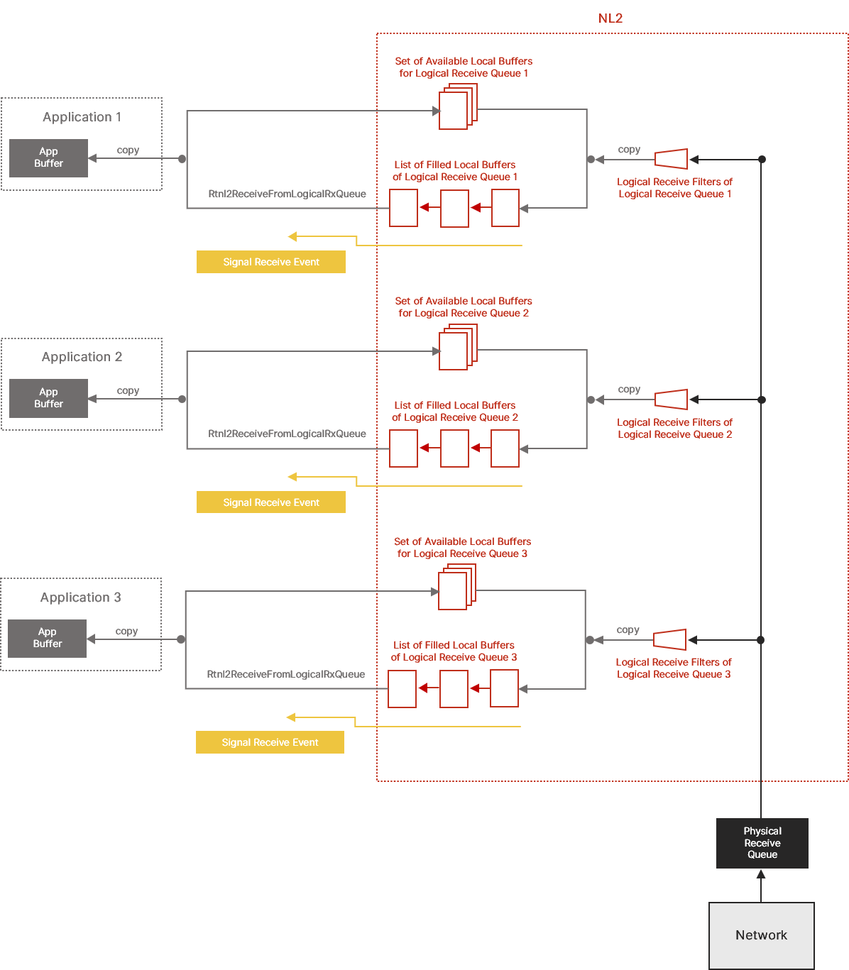
Relationship Between Logical Receive Queues
The diagram below illustrates how data flows from the Hardware Buffers to the application buffers when several Logical Receive Queues are sitting on top of the same Physical Receive Queue:
Transmitting Frames with the Shared Queue Access Method
Introduction
An application can use two methods to transmit Ethernet frames through a Physical Transmit Queue: the Shared Queue Access method and the Exclusive Queue Access method. In this section, we will discuss the Shared Queue Access method.
Note: A given Physical Transmit Queue can't be used simultaneously in both Shared and Exclusive Access modes.
With the Shared Queue Access method, multiple applications can use the same Physical Transmit Queue simultaneously. The NL2 synchronizes and arbitrates the different transmit requests received in parallel.
Every application that wants to use a given Physical Transmit Queue in Shared Access mode needs to create a Logical Transmit Queue on top of it. A Logical Transmit Queue is like a virtual channel inside a Physical Transmit Queue.
The Shared Queue Access method is well suited to applications that don’t require deterministic latency. This typically includes TCP/IP stacks, IEEE Control protocols (such as PTP, LLDP, SRP, and AVDECC), and proprietary control protocols.
Workflow
This workflow outlines how to work with Logical Transmit Queues:
- Select the Interface to use and call Rtnl2OpenInterface to get a handle to that Interface.
- Select the Physical Transmit Queue to use and call Rtnl2CreateLogicalTxQueue to create a Logical Transmit Queue on top of it.
- If needed, call Rtnl2EnableLogicalTxQueueTimestamping to enable the timestamping logic on this Logical Transmit Queue. This function returns an Egress Timestamp event.
- Repeat the following whenever a packet needs to be transmitted, until the application needs to be terminated:
- Fill in a memory block with the content of the packet to be sent (including the Ethernet header, but not the FCS).
- Populate the pFrameData and FrameLength fields of an RTNL2_TRANSMIT_DESC structure.
- If this packet needs to be timestamped on egress, set the EgressTimestampRequired field to TRUE.
- Call Rtnl2TransmitOverLogicalTxQueue.
- If egress timestamping was requested, wait for the Egress Timestamp Event and then call Rtnl2GetLogicalTxQueueTimestamp to retrieve the egress timestamp.
- Destroy the Logical Transmit Queue with Rtnl2DestroyLogicalTxQueue.
Creating a Logical Transmit Queue
A Logical Transmit Queue can be created on top of a Physical Transmit Queue only if another process has NOT already acquired the Physical Transmit Queue. To create a Logical Transmit Queue, call Rtnl2CreateLogicalTxQueue.
The Rtnl2CreateLogicalTxQueue function takes a valid handle to the interface (see Rtnl2OpenInterface), the index of the Physical Transmit Queue, and a buffer count as parameters. The buffer count is the number of local buffers the NL2 allocates for this Logical Transmit Queue. These local buffers hold pending-to-transmit frames and are dedicated to this Logical Transmit Queue, which means they are not shared with other Logical Transmit Queues. This guarantees that an application will not starve another one by using all its buffers. However, this doesn’t prevent an application from slowing others by transmitting many frames and thus using most of the hardware resources (DMA descriptors and link bandwidth).
Note: After getting a Logical Transmit Queue handle, the application can safely close the interface handle with Rtnl2CloseInterface if it no longer needs it. This will not invalidate the Logical Transmit Queue handle.
Enabling the Timestamping Logic on a Logical Transmit Queue
Egress timestamping occurs on a per-frame basis upon request from the application. However, before the application can request egress timestamping for a frame transmitted through a Logical Transmit Queue, the timestamping logic must be enabled on that Logical Transmit Queue. For that, two conditions must be met:
- The user must enable timestamping on the underlying Physical Transmit Queue through some static configuration in the wRTOS Settings.
- The application must successfully call Rtnl2EnableLogicalTxQueueTimestamping on that Logical Transmit Queue.
When these two conditions are met, the application can decide whether the hardware should timestamp each frame it transmits through that Logical Transmit Queue.
The Rtnl2EnableLogicalTxQueueTimestamping function returns a handle to an Event. The NL2 signals this event in two different cases:
- Either a frame has been successfully transmitted and timestamped,
- Or the last to-be-timestamped frame has not been timestamped due to the link being down or some other hardware issue, causing the NL2 to abort the operation.
In both cases above, the application should call the Rtnl2GetLogicalTxQueueTimestamp function to determine why the event was signaled and retrieve the Egress Timestamp in case there is a valid one.
When using Egress Timestamping through a Logical Transmit Queue, the application should NOT use its timeout because the NL2 already implements one. It will automatically abort the timestamping operation if the hardware doesn't report a valid timestamp within a reasonable time after the corresponding buffer has been consumed.
Note: After enabling the timestamping logic on a Logical Transmit Queue, it remains enabled until the Logical Transmit Queue is destroyed. There is no such function as Rtnl2DisableLogicalTxQueueTimestamping.
Transmitting a Frame over a Logical Transmit Queue
To transmit a frame, the application first prepares the frame’s content (including the 14-byte Ethernet header and the payload, but NOT the final 4-byte FCS or the potential 4-byte VLAN Tag) in its buffer, which may be statically or dynamically allocated.
Then, it populates an RTNL2_TRANSMIT_DESC structure, which describes the transmit operation, and calls Rtnl2TransmitOverLogicalTxQueue.
The Rtnl2TransmitOverLogicalTxQueue function behaves differently depending on whether a Hardware Buffer is available when the function is called or not:
- If a Hardware Buffer is available, the function copies the frame’s content into the Hardware Buffer and inserts it into the Hardware Transmit Queue. In this case, only one copy of the user data is made.
- If no Hardware Buffer is available, the function finds an available local buffer, copies the frame’s content into this local buffer, and inserts it into the list of pending local buffers. Later (either the next time an application calls Rtnl2TransmitOverLogicalTxQueue, or asynchronously in a background thread of the NL2), if a Hardware Buffer becomes available, the NL2 will copy the content of the pending local buffer into the Hardware Buffer and insert it into the Hardware Transmit Queue. In this case, two copies of the user data are made.
The Rtnl2TransmitOverLogicalTxQueue function fails if, when it is called, there are already BufferCount inflight buffers holding content from this Logical Transmit Queue, where BufferCount is the parameter supplied to Rtnl2CreateLogicalTxQueue.
If needed, the application can request the insertion of a VLAN Tag in the transmitted frame by setting RTNL2_TRANSMIT_DESC.TaggedFrame to TRUE and providing the VLAN Tag value in RTNL2_TRANSMIT_DESC.VlanTag.
The NL2 does NOT allow an application to transmit a new to-be-timestamped frame until the previous timestamping operation is finished. The application MUST respect the following sequence:
- If there is no need to timestamp on transmit, transmit frames by calling Rtnl2TransmitOverLogicalTxQueue with RTNL2_TRANSMIT_DESC.EgressTimestampRequired set to FALSE.
- If a frame needs to be timestamped on transmit, transmit it by calling Rtnl2TransmitOverLogicalTxQueue with RTNL2_TRANSMIT_DESC.EgressTimestampRequired set to TRUE.
If the function returns an error, return to step 1 (do NOT wait for the Egress Timestamp event because the NL2 will never signal it in that case). - Wait until the NL2 sets the Egress Timestamp event.
- While waiting for the Egress Timestamp to be signaled, the application can still transmit frames with RTNL2_TRANSMIT_DESC.EgressTimestampRequired set to FALSE.
- Call Rtnl2GetLogicalTxQueueTimestamp.
- Go to step 1.
Note: The NL2 can manage simultaneous Egress Timestamping requests on the same Physical Transmit Queue if they come from multiple Logical Transmit Queues on top of that Physical Transmit Queue. This allows multiple independent applications to use the Egress Timestamping feature on top of the same hardware queue.
However, it is not allowed to make simultaneous Egress Timestamping requests through the same Logical Transmit Queue.
Monitoring and Extracting Egress Timestamps
The application should do the following after every successful call to Rtnl2TransmitOverLogicalTxQueue with RTNL2_TRANSMIT_DESC.EgressTimestampRequired set to TRUE:
- Wait until the NL2 sets the Egress Timestamp event.
- Call Rtnl2GetLogicalTxQueueTimestamp.
It’s up to the application to decide whether to wait for the Egress Timestamp event or handle it asynchronously so that other general frames can be transmitted while waiting for it to be set.
In any case, the NL2 will ALWAYS set the Egress Timestamp after every successful call to Rtnl2TransmitOverLogicalTxQueue with RTNL2_TRANSMIT_DESC.EgressTimestampRequired set to TRUE. Either because the hardware reported a valid timestamp, or because the hardware reported an issue or didn’t report anything within a reasonable amount of time after the corresponding buffer has been consumed by the hardware queue.
If the application calls Rtnl2GetLogicalTxQueueTimestamp before the NL2 signals the Egress Timestamp event, or if the application calls Rtnl2GetLogicalTxQueueTimestamp twice in a row, then the function fails with the ERROR_INVALID_DATA error code. Otherwise, unless some other unexpected errors occur (see Rtnl2GetLogicalTxQueueTimestamp for details), the function will do one of the following:
- Succeed and return a valid Egress Timestamp.
- Fail with the ERROR_IO_DEVICE error code, which means that the NL2 has aborted the Egress Timestamping operation due to reasons such as the link being down, expiration of the timeout, or other hardware-specific issues.
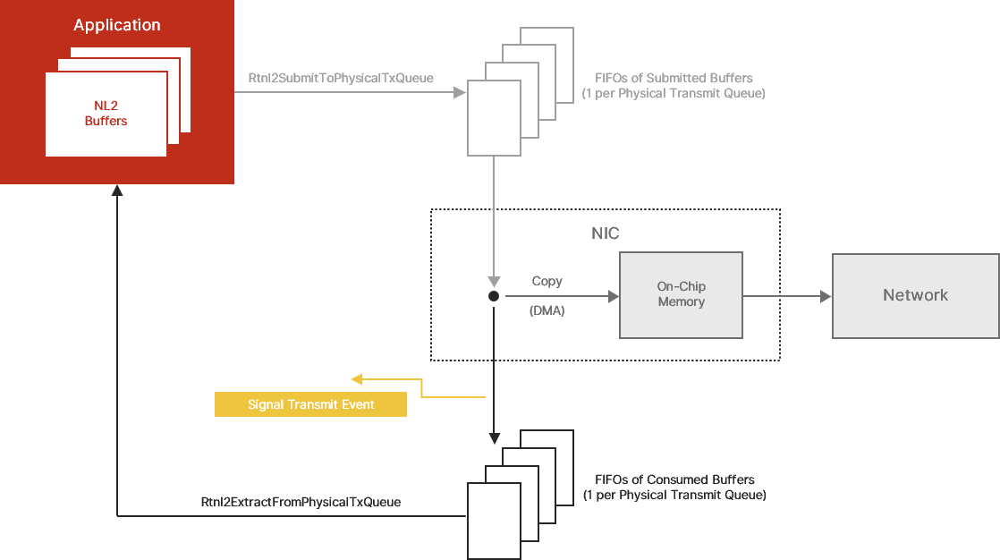
Relationship between Logical Transmit Queues
The diagram below illustrates how data flows from the application buffers to the Hardware Buffers when multiple Logical Transmit Queues are sitting on top of the same Physical Transmit Queue:
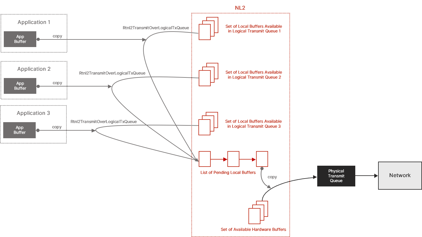
Note: The diagram shows the data flow when two copies are involved, but there is only one copy when a Hardware Buffer is immediately available when the application calls Rtnl2TransmitOverLogicalTxQueue.
Working with NL2 Buffers
This section is relevant for the Exclusive Queue Access method only (see Receive Frames with the Exclusive Queue Access Method and Transmit Frames with the Exclusive Queue Access Method). In this method, the application exchanges Ethernet frames with the NL2 through NL2 Buffers.
An NL2 Buffer is an area of memory that can be directly used by the underlying hardware to store or load an Ethernet frame.
Every NL2 Buffer is associated with only one Physical Receive Queue or Physical Transmit Queue of an Interface. The NL2 allocates all NL2 Buffers for all Physical Receive Queues and Physical Transmit Queues of all interfaces at startup. The NL2 guarantees that the allocated buffers meet the underlying hardware requirements regarding memory alignment and base address. The NL2 releases NL2 buffers when it terminates.
All the NL2 Buffers allocated for all the Physical Receive Queues of the same interface have the same size, equal to RTNL2_INTERFACE_FEATURES.RxBufferLength.
All the NL2 Buffers allocated for all the Physical Transmit Queues of the same interface have the same size, equal to RTNL2_INTERFACE_FEATURES.TxBufferLength.
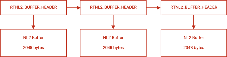
Every NL2 Buffer is described by an NL2 Buffer Header structure called RTNL2_BUFFER_HEADER. The NL2 allocates the RTNL2_BUFFER_HEADER structures. To ensure backward and forward compatibility, the NL2 uses the BufferHeaderStructSize value provided by the application in the call to Rtnl2AcquirePhysicalRxQueue or Rtnl2AcquirePhysicalTxQueue to allocate NL2 Buffer Headers of the right size. The Buffer Header contains the virtual address of the NL2 Buffer, and it can be linked with other Buffer Headers to create lists of NL2 Buffers:
The diagram below shows 3 NL2 Buffers of 2048 bytes each, linked together due to their buffer headers:
Receiving Frames with the Exclusive Queue Access Method
Introduction
An application can use two methods to receive Ethernet frames through a Physical Receive Queue: the Exclusive Queue Access method and the Shared Queue Access method. In this section, we will discuss the Exclusive Queue Access method.
Note: A Physical Receive Queue can't simultaneously be used in both Shared and Exclusive Access modes.
Note: A Physical Receive Queue cannot be used in Exclusive Access mode if a filter driver is enabled on it.
With the Exclusive Queue Access method, only one application can use the Physical Receive Queue at a time. Obtaining exclusive access to a Physical Receive Queue is called acquisition.
The Exclusive Queue Access method is well suited to applications that require deterministic latency, typically TSN applications.
Note: If you are implementing a control protocol, you probably don’t need deterministic latency. You should consider using the Shared Queue Access method, which is simpler and more flexible than the Exclusive Queue Access method.
General Workflow
This workflow outlines how general network applications should use Physical Receive Queues:
- Select the Interface to use and call Rtnl2OpenInterface to get a handle to that Interface.
- Select the Physical Receive Queue to use and call Rtnl2AcquirePhysicalRxQueue to get exclusive access to that Physical Receive Queue.
- Configure the operating mode of the Physical Receive Queue with Rtnl2SetPhysicalRxQueueMode.
- Configure the Multicast Hash Filter with Rtnl2SetPhysicalRxQueueMulticastFilter.
- If needed, enable the timestamping logic on this Physical Receive Queue by calling Rtnl2EnablePhysicalRxQueueTimestamping.
- Create the Receive event by calling Rtnl2CreatePhysicalRxQueueEvent.
- Repeat the following until the application needs to terminate:
- Wait on the Receive event handle returned by Rtnl2CreatePhysicalRxQueueEvent.
- Call Rtnl2ExtractFromPhysicalRxQueue in a loop until it returns ERROR_NO_DATA. This extracts the filled NL2 Buffers from the Physical Receive Queue.
- Process the extracted NL2 Buffers.
- Call Rtnl2SubmitToPhysicalRxQueue to submit all the extracted NL2 Buffers to the Physical Receive Queue.
- Destroy the Receive event by calling Rtnl2DestroyPhysicalRxQueueEvent.
- Release the Physical Receive Queue by calling Rtnl2ReleasePhysicalRxQueue.
Workflow for Cyclic Applications
Cyclic applications send packets and process received packets at precise intervals.
These applications can be optimized by not using the Receive event but instead polling the state of the Physical Receive Queue every cycle. This saves several context switches that would otherwise occur randomly within each cycle.
The workflow is as follows:
- Select the Interface to use and call Rtnl2OpenInterface to get a handle to that Interface.
- Select the Physical Receive Queue to use and call Rtnl2AcquirePhysicalRxQueue to get exclusive access to that Physical Receive Queue.
- Configure the operating mode of the Physical Receive Queue by calling Rtnl2SetPhysicalRxQueueMode.
- Configure the Multicast Hash Filter with Rtnl2SetPhysicalRxQueueMulticastFilter.
- If needed, enable the timestamping logic on this Physical Receive Queue by calling Rtnl2EnablePhysicalRxQueueTimestamping.
- Repeat the following until the application needs to terminate:
- Wait for the next cycle.
- Call Rtnl2ExtractFromPhysicalRxQueue in a loop until it returns ERROR_NO_DATA. This extracts the filled NL2 Buffers from the Physical Receive Queue.
- Process the extracted NL2 Buffers.
- Call Rtnl2SubmitToPhysicalRxQueue to submit all the extracted NL2 Buffers to the Physical Receive Queue.
- Release the Physical Receive Queue by calling Rtnl2ReleasePhysicalRxQueue.
Advanced Concepts Related to Physical Receive Queues
NL2 Receive Buffers' State
NL2 Buffers associated to Physical Receive Queues can be in one of the two following states:
- Either owned by the NL2,
- Or owned by the application.
By default, at startup, all allocated NL2 Receive Buffers are owned by the NL2. Later, these buffers are filled by the NIC, and the application takes ownership by calling Rtnl2ExtractFromPhysicalRxQueue. The application then transfers ownership back to the NL2 by calling Rtnl2SubmitToPhysicalTxQueue.
The NL2 enforces strict rules about when the application can pass an NL2 Buffer to an API function. Any call to Rtnl2SubmitToPhysicalRxQueue will fail if the application does not currently own the passed buffer(s).
NL2 Receive Buffers' Flow
The diagram below shows the flow of NL2 Receive Buffers between the application, the NL2, and the NIC hardware:
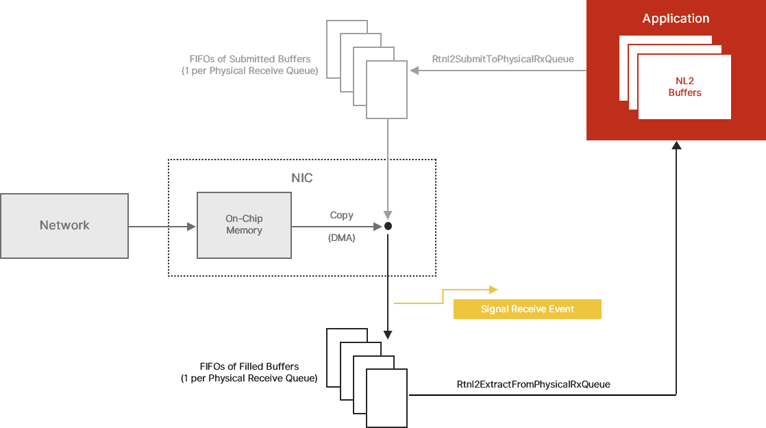
FIFOs of Submitted Buffers and Filled Buffers
The NL2 exposes a model of a NIC in which each Physical Receive Queue is composed of a series of two FIFOs of NL2 Buffers:
- A FIFO of submitted buffers, and
- A FIFO of filled buffers
“Filled” buffers are those that the NIC has filled with the content of incoming Ethernet frames. They are ready for the application to extract. If the application has enabled the Receive event, then the NL2 signals this event every time a buffer is inserted in the FIFO of filled buffers.
Submitted buffers are those the application has processed and returned to the NIC. They are ready for the NIC to fill as soon as new Ethernet frames arrive from the network.
On-Chip Memory
Every NIC has an internal buffer that temporarily stores incoming frame data while it is copied to the NL2 Buffers. Some NICs have a small internal buffer (less than the size of an Ethernet frame), while others have an internal buffer that can contain multiple Ethernet frames.
In the NL2 model, the following atomic sequence occurs whenever the internal buffer is not empty and there is at least one NL2 Buffer in the FIFO of submitted buffers:
- The NIC extracts one NL2 Buffer from the FIFO of submitted buffers.
- The NIC fills the NL2 Buffer with the content of the on-chip memory.
- The NIC inserts the NL2 Buffer into the FIFO of filled buffers.
Acquiring a Physical Receive Queue
To acquire a Physical Receive Queue, the application must have a valid handle to the interface (see Rtnl2OpenInterface) and know the index of the Physical Receive Queue to acquire. Then, the application calls Rtnl2AcquirePhysicalRxQueue. The function fails if another application has already acquired the specified queue or if it is currently used in Shared Queue Access mode. Otherwise, it returns a handle to the Physical Receive Queue, that can be used for all subsequent operations on the queue.
Note: After getting a Physical Receive Queue handle, the application can safely close the interface handle with Rtnl2CloseInterface if it's no longer needed. This will not invalidate the Physical Receive Queue handle.
The Rtnl2AcquirePhysicalRxQueue function not only marks the Physical Receive Queue as acquired by the calling application but also cleans up the Physical Receive Queue so that all buffers that may be in the FIFO of filled buffers at that point are automatically moved to the FIFO of submitted buffers. This ensures that the application gets the queue in a known state before using it: the FIFO of submitted buffers is full, and the FIFO of filled buffers is empty.
Configuring the Operating Mode
Some interfaces can operate in a non-nominal mode depending on the underlying hardware. The current operating mode is represented by a set of settings that can be turned on or off. In the nominal mode, which is the default when the interface is started, all settings are turned off.
The application can dynamically turn the settings on or off independently, thus making the interface operate in a non-nominal mode. The available settings are as follows:
Promiscuous mode:
- When this mode is turned off, incoming frames with the following Destination MAC Addresses are filtered out by the hardware:
- Unicast Addresses which are not equal to the MAC Address of the NIC.
- Multicast Addresses which don’t pass the Multicast Hash filter (see below).
- When this mode is turned on, incoming frames are never filtered out based on their Destination MAC Address.
Pass bad frames mode:
- When this mode is turned off, the hardware filters out incoming frames marked as “bad frames” by the NIC.
- When this mode is turned on, incoming frames marked as “bad frames” by the NIC are not filtered out.
While these settings apply globally at the interface level, the NL2 exposes them at the queue level. This is because each different application owning a different queue of the same interface may have different requirements. For instance, one application may want to enable promiscuous mode while others may not.
To set the interface mode settings using a Physical Receive Queue handle, the application must call Rtnl2SetPhysicalRxQueueMode.
To set the interface mode settings using a Logical Receive Queue handle, the application must call Rtnl2SetLogicalRxQueueMode.
The NL2 maintains a per-queue copy of each interface mode setting. When an application calls one of the two functions above, the NL2 does not directly update the state of the hardware. It first updates the proper per-queue copy. Then it does a logical OR of the per-queue settings of all the Physical and Logical Receive Queues of the Interface. Finally, it updates the hardware if the result is different than before.
For example, if one application requests that Promiscuous be turned on while another requests that it be turned off, the logical OR will be TRUE, so the NL2 will turn Promiscuous mode on in the hardware. If the two applications request that Promiscuous be turned off, then the NL2 will turn Promiscuous mode off in the hardware.
Note: When the application terminates, the NL2 automatically resets all interface mode settings of the queues owned by that application to their default (i.e. turned off). If this changes the logical OR of all per-queue settings, then the NL2 disables the setting at the hardware level.
In addition to Rtnl2SetPhysicalRxQueueMode and Rtnl2SetLogicalRxQueueMode, the NL2 also provides the Rtnl2GetPhysicalRxQueueMode and Rtnl2GetLogicalRxQueueMode functions, which return two pieces of information:
- The state requested by this application for this setting through this queue handle.
- The current state of the hardware (i.e., the logical OR of all per-queue settings).
Configuring the Multicast Hash Filter
Every NIC hardware implements a Multicast Hash Filter, also called an imperfect filter, or inexact filter.
The Multicast Hash Filter is one of the first stages every incoming frame goes through on the Receive path. It checks the first bit of the Destination MAC Address to determine whether it’s a Multicast Address; if so, it calculates a hash value based on the 6 bytes of the Destination MAC Address. This hash value serves as an index in a table of bits. If the bit at the specified index is 0, the Multicast Hash Filter discards the incoming frame immediately. Otherwise, it lets the frame pass to the next stage of the Receive path.
Every hardware has an algorithm, such as Ethernet CRC32, to compute the hash value associated with a Multicast MAC Address. The Ethernet CRC32 is the same algorithm used to compute the FCS of every Ethernet frame. It provides a 32-bit value, but the NIC generally takes only a few bits from that, which are used as the index in the bits table. A common size for the hash index is 5 bits, allowing a table of 64 bits to be addressed. Some hardware can use more bits. The bigger the table, the less probability that undesired Multicast Addresses will pass the filter.
By default, the table of bits of the Multicast Hash Filter is initialized with all 0’s, which means that no Multicast frame is allowed to pass. However, applications can dynamically request the NL2 to update a list of allowed Multicast Addresses, setting some of the bits of that hardware table to 1.
Although one table of bits per interface exists, the NL2 exposes Multicast Filter configuration functions at the queue level. This is because each different application owning a different queue of the same interface may have different requirements; one process may want to receive some Multicast Addresses while others may want to receive different Multicast Addresses or no Multicast Addresses at all. The NL2 keeps, for each queue, the list of Multicast Addresses that the application owning that queue has requested. Whenever an application updates its list, the NL2 re-builds the list of all Multicast Addresses to let pass by re-aggregating all the lists from all queues. Then it gives this aggregated list to the NIC driver, which is responsible for updating the hardware table of bits in the Multicast Hash Filter of the interface.
The application must call Rtnl2SetPhysicalRxQueueMulticastFilter to set the list of allowed Multicast Addresses using a Physical Receive Queue handle.
The application must call Rtnl2SetLogicalRxQueueMulticastFilter to set the list of allowed Multicast Addresses using a Logical Receive Queue handle.
Note: When an application terminates, the NL2 automatically destroys the list of allowed Multicast Addresses that was associated with the queues owned by that application and then calls the NIC driver to potentially update the hardware table of bits of the Multicast Hash Filter.
Enabling the Timestamping Logic on a Physical Receive Queue
The application does not decide whether to enable the hardware timestamping logic in the NIC or what specific rules the hardware applies to determine which incoming frame must be timestamped. The user makes that decision through some static configuration in the wRTOS Settings.
If the user configured hardware timestamping for a given Interface in the wRTOS Settings, then the NL2 enables hardware timestamping and the associated rules at the NIC's startup. The logic runs regardless of whether an application wants to use it at a given time.
Suppose the user didn’t enable hardware timestamping in the wRTOS Settings. In this ase, the NL2 does not enable hardware timestamping at the NIC's startup, and the logic remains stopped forever, regardless of whether an application wants to use it at a given time.
Another decision the user makes through interface configuration in the wRTOS Settings is which of the Physical Receive Queues will report the ingress timestamps in the buffers of received frames. The NL2 will enable this only on the Physical Receive Queues marked to be time aware.
At any time, an application can call Rtnl2EnablePhysicalRxQueueTimestamping. The function takes the handle to an acquired Physical Receive Queue as a parameter and does the following:
- Check if the NIC supports hardware timestamping; if not, return an error.
- Check if the NIC has been configured in the wRTOS Settings to enable hardware timestamping; if not, return an error
- Check if the Physical Receive Queue has been configured in the wRTOS Settings to be time-aware; if not, return an error
- If all the verifications above pass, the Physical Receive Queue enables timestamping.
When a Physical Receive Queue has timestamping enabled, the NL2 puts the value of the ingress timestamp in the associated RTNL2_BUFFER_HEADER for every incoming frame timestamped by the hardware.
Note: The Rtnl2EnablePhysicalRxQueueTimestamping function does NOT change anything to the hardware; it simply notes that the buffers containing timestamped frames from this Physical Receive Queue object need to contain the timestamp.
Monitoring the FIFO of Filled Buffers
Although not mandatory, a common way of dealing with incoming frames is to enable the hardware Receive interrupt, which the NL2 turns into event notifications.
By calling the Rtnl2CreatePhysicalRxQueueEvent, the application requests the creation of an Event object that will be signaled by the NL2 whenever the NIC triggers the corresponding hardware interrupt. The function returns the handle to the created event, which the application can use in subsequent calls to RtWaitForSingleObject or RtWaitForMultipleObjects.
When the application no longer needs to monitor the filled buffers of a Physical Receive Queue, it must destroy the Receive Event by calling Rtnl2DestroyPhysicalRxQueueEvent.
Note: The NL2 doesn’t enable the hardware interrupt of a given Physical Receive Queue until the application requests the creation of the Receive event.
Note: If interrupt moderation is enabled on the hardware interrupt, the Receive event may not be signaled for every buffer inserted in the FIFO of filled buffers.
Note: The application must NOT assume that the signaling of the Receive event means that new buffers are available in the FIFO of filled buffers. It must gracefully handle the situation where the event is signaled, but there are no newly filled buffers. This can happen because the event is signaled asynchronously.
Reciprocally, when the event is signaled, the application MUST extract all the available filled buffers (in one or more calls to Rtnl2ExtractFromPhysicalRxQueue) because the event is signaled only based on the insertion of new buffers in the FIFO of filled buffers, not based on whether the FIFO of filled buffers is empty or not.
Extracting the Filled Buffers
When an Ethernet frame arrives from the wire (at link speed), its content is stored inside the NIC on-chip memory. The time it takes to complete this operation depends on the frame's length and the link's speed. For example, it takes about 120 us to receive a 1500-byte frame over a 100 Mbps link.
Then, the Hardware Dispatcher of the NIC decides which Physical Receive Queue will receive the frame (see Configure the Hardware Dispatcher). If the target FIFO of submitted buffers is not empty, then the following actions occur:
- The frame's content is copied from the NIC's on-chip memory to the FIFO of filled buffers (sitting in system memory); this copy is done in hardware by the NIC's DMA.
- If Receive interrupts are enabled, the NIC generates an interrupt, and the NL2 signals the Receive Event.
If a frame is received from the wire and the target submitted FIFO is empty, the hardware silently discards it.
The application can retrieve all filled buffers in one call to the Rtnl2ExtractFromPhysicalRxQueue function. The buffers are returned in the order the NIC filled them.
After retrieving a buffer with Rtnl2ExtractFromPhysicalRxQueue, the NL2 no longer manipulates it, allowing the application to use it freely. In general, the application will process it and resubmit it to the Physical Receive Queue so that the FIFO of submitted buffers doesn’t empty, and the hardware doesn’t have to discard incoming frames.
If no filled buffer is available when the application calls Rtnl2ExtractFromPhysicalRxQueue, the function returns a NULL pointer for the list of extracted buffers but does NOT fail (it returns TRUE).
IMPORTANT: The application is NOT allowed to reuse a buffer that has been provided to Rtnl2SubmitToPhysicalRxQueue but has not yet been returned by Rtnl2ExtractFromPhysicalRxQueue. If the application provides the same buffer twice to Rtnl2SubmitToPhysicalRxQueue without getting it back from Rtnl2ExtractFromPhysicalRxQueue, the call to Rtnl2SubmitToPhysicalRxQueue will fail, even if the buffer was filled by the hardware in the meantime.
Note: The Rtnl2ExtractFromPhysicalRxQueue function doesn’t involve any copy. This allows zero copy frame reception.
Submitting Buffers
After processing the extracted buffers, the application returns the ownership to the NL2 by calling Rtnl2SubmitToPhysicalRxQueue. This function inserts the supplied NL2 Buffers in the FIFO of submitted buffers of the Physical Receive Queue and immediately returns.
Note: A successful return from Rtnl2SubmitToPhysicalRxQueue does NOT mean that any frame has been received. The buffers have been made available for the NIC, which will fill them as soon as frames arrive from the wire.
The application can provide any number of buffers in a single call to Rtnl2SubmitToPhysicalRxQueue. The application provides the address of the first buffer header of a linked list. The NL2 goes through that list and inserts all the buffers in the FIFO of submitted buffers.
Releasing the Physical Receive Queue
After an application has finished using a Physical Receive Queue, it must release it so another application can use it.
To release a Physical Receive Queue, call Rtnl2ReleasePhysicalRxQueue.
The NL2 expects the application to fully terminate all the activities related to that queue before calling Rtnl2ReleasePhysicalRxQueue. In particular, the application must destroy the Receive event associated with that queue, if it created one.
The NL2 also expects the application to submit back all the Receive Buffers that it still owns before calling Rtnl2ReleasePhysicalRxQueue.
Precautions to Take Before Processing an Extracted Buffer
About Unfiltered Frames
Unlike Logical Receive Queues, the NL2 does NOT implement software filtering on the Ethernet packets returned to the application by Rtnl2ExtractFromPhysicalRxQueue function. This design choice minimizes the receive latency to the lowest level the hardware allows.
Therefore, the following scenarios can happen:
- The application turned Promiscuous mode off but still receives packets whose Destination MAC Address is not the MAC Address of the NIC.
- This can happen if another application using another Physical/Logical Receive Queue of the same interface has turned Promiscuous mode on.
- Suggested mitigation, if necessary: check the Destination MAC Address in every extracted buffer.
- The application turned PassBadFrames mode off but still receives packets marked as “bad frames” by the NIC.
- This can happen if another application using another Physical/Logical Receive Queue of the same interface has turned the PassBadFrames mode on.
- Suggested mitigation, if necessary: check the BadFrame field of the RTNL2_BUFFER_HEADER of every extracted buffer.
- The application disabled the reception of Multicast packets but still receives Multicast packets.
- This can happen if another application using another Physical/Logical Receive Queue of the same interface has enabled the reception of Multicast packets.
- Suggested mitigation, if necessary: check the Destination MAC Address in every extracted buffer.
- The application has set an EtherType Dispatch rule to receive a given EtherType but still receives different EtherTypes.
- This can happen if the Physical Receive Queue is the default receive queue or another application has set additional EtherType Dispatch rule(s) to forward other EtherTypes to that queue.
- Suggested mitigation, if necessary: check the EtherType in every extracted buffer.
- The application hasn't set any EtherType Dispatch rule to receive IP packets (0x0800) nor any UDP Port Dispatch rule to receive UDP packets with a specific UDP Destination Port but still receives UDP packets.
- This can happen if the Physical Receive Queue is the default receive queue or another application has set UDP Port Dispatch rule(s) to forward specific UDP Destination Ports to that queue.
- Suggested mitigation, if necessary: check the EtherType and UDP Destination Port in every extracted buffer.
About Junk Frames
It can also happen that a receive operation fails at the hardware level but still utilizes a submitted buffer and fills it with junk data. In this case, the NL2 does NOT filter such a buffer. Instead, it sets the Junk field of the RTNL2_BUFFER_HEADER to TRUE and returns the junk buffer to the application in a subsequent call to Rtnl2ExtractFromPhysicalRxQueue.
The application MUST check the Junk field of every extracted NL2 Buffer and immediately re-submit any buffer with the Junk field set to TRUE without processing it.
Transmitting Frames with the Exclusive Queue Access Method
Introduction
An application can use two methods to transmit Ethernet frames through a Physical Transmit Queue: the Exclusive Queue Access method and the Shared Queue Access method. In this section, we will discuss the Exclusive Queue Access method.
Note: A given Physical Transmit Queue can't simultaneously be used in both Shared and Exclusive Access modes.
With the Exclusive Queue Access method, only one application can use the Physical Transmit Queue at a time. Obtaining exclusive access to a Physical Transmit Queue is called acquisition.
The Exclusive Queue Access method is well suited to applications that require deterministic latency, typically TSN applications.
Note: If you are implementing a control protocol, you probably don’t need deterministic latency. Thus, you should consider using the Shared Queue Access method, which is simpler and more flexible than the Exclusive Queue Access method.
General Workflow
This workflow outlines how general network applications should use Physical Transmit Queues:
- Select the Interface to use and call Rtnl2OpenInterface to get a handle to that Interface.
- Select the Physical Transmit Queue to use and call Rtnl2AcquirePhysicalTxQueue to get exclusive access to that Physical Transmit Queue.
- If needed, enable the timestamping logic on this Physical Transmit Queue by calling Rtnl2EnablePhysicalTxQueueTimestamping; this function returns an Egress Timestamp Event.
- Get a set of available NL2 Buffers by calling Rtnl2GetPhysicalTxQueueBuffers.
- Spawn a thread that does the following in background:
- Create the Transmit event by calling Rtnl2CreatePhysicalTxQueueEvent.
- Repeat the following until the application needs to terminate:
- Wait on the Transmit event handle returned by Rtnl2CreatePhysicalTxQueueEvent.
- Call Rtnl2ExtractFromPhysicalTxQueue in a loop until it returns an empty list of NL2 Buffers. This extracts the consumed NL2 Buffers from the Physical Transmit Queue.
- Insert the extracted NL2 Buffers into the set of available NL2 Buffers.
- Destroy the Transmit event by calling Rtnl2DestroyPhysicalTxQueueEvent.
- Repeat the following whenever a packet needs to be transmitted until the application needs to terminate:
- Check that the set of available NL2 Buffers is not empty and take one of them.
- If the set is empty, drop the packet (or keep it to retry later if the implemented protocol supports this option).
- Fill in the NL2 Buffer with the content of the Ethernet frame to transmit (including the Ethernet header but not the FCS).
- Populate the NL2 Buffer header with the length of the frame.
- If this packet needs to be timestamped on egress, set the EgressTimestampRequired field to TRUE.
- Call Rtnl2SubmitToPhysicalTxQueue.
- If egress timestamping is required, wait on the Egress Timestamp Event and call Rtnl2GetPhysicalTxQueueTimestamp to retrieve the egress timestamp.
- Check that the set of available NL2 Buffers is not empty and take one of them.
- Return the set of available NL2 Buffers by calling Rtnl2ReturnPhysicalTxQueueBuffers.
- Release the Physical Transmit Queue by calling Rtnl2ReleasePhysicalTxQueue.
Workflow for Cyclic Applications
Cyclic applications send packets and process received packets at precise regular intervals.
These applications can be optimized by not using the Transmit event but instead polling the state of the Physical Transmit Queue every cycle. This saves several context switches that would otherwise occur randomly within every cycle.
The workflow is as follows:
- Select the Interface to use and call Rtnl2OpenInterface to get a handle to that Interface.
- Select the Physical Transmit Queue to use and call Rtnl2AcquirePhysicalTxQueue to get exclusive access to that Physical Transmit Queue.
- If needed, enable the timestamping logic on this Physical Transmit Queue by calling Rtnl2EnablePhysicalTxQueueTimestamping; this function returns an Egress Timestamp Event.
- Get a set of available NL2 Buffers by calling Rtnl2GetPhysicalTxQueueBuffers.
- Repeat the following until the application needs to terminate:
- Wait for the next cycle.
- If the set of available NL2 Buffers is not empty, take one of them. Otherwise, call Rtnl2ExtractFromPhysicalTxQueue to reclaim a buffer already consumed by the NIC.
- If Rtnl2ExtractFromPhysicalTxQueue returns an empty list of NL2 Buffers, skip this cycle (this should never happen if the queue has been provisioned with sufficient buffers, except when the link is down).
- Fill in the NL2 Buffer with the content of the Ethernet frame to transmit (including the Ethernet header but not the FCS).
- Populate the NL2 Buffer header with the length of the frame.
- If this packet needs to be timestamped on egress, set the EgressTimestampRequired field to TRUE.
- Call Rtnl2SubmitToPhysicalTxQueue.
- If egress timestamping was requested, wait on the Egress Timestamp Event and call Rtnl2GetPhysicalTxQueueTimestamp to retrieve the egress timestamp.
- Return the set of available NL2 Buffers by calling Rtnl2ReturnPhysicalTxQueueBuffers.
- Release the Physical Transmit Queue by calling Rtnl2ReleasePhysicalTxQueue.
Note: In the sequence above, the application sends one Ethernet packet at every cycle, but real-life applications generally need to send a batch of Ethernet packets at every cycle. In that case, link the NL2 Buffers together in a list and provide the head of the list to the Rtnl2SubmitToPhysicalTxQueue function.
Advanced Concepts Related to Physical Transmit Queues
NL2 Transmit Buffers’ State
Before transmitting frames using the Physical Transmit Queue APIs, the application must get one or more available NL2 Buffers by calling the Rtnl2GetPhysicalTxQueueBuffers function. To return NL2 Buffers to the NL2, the application must call Rtnl2ReturnPhysicalTxQueueBuffers.
The Rtnl2GetPhysicalTxQueueBuffers function returns the address of a buffer header. If the application requested more than one buffer, this buffer header is the head of a linked list. When calling Rtnl2ReturnPhysicalTxQueueBuffers, the application also provides the address of a buffer header. The application does not have to return buffers in the same order as it got them in the first place.
At any given point in time, an NL2 Transmit Buffer is in one of the two following states:
- Owned by the NL2
- Owned by the application.
By default, all freshly allocated NL2 Transmit Buffers are owned by the NL2 at startup. Later, the NL2 transfers ownership to the application when the application calls Rtnl2GetPhysicalTxQueueBuffers. With the NL2 Transmit Buffers that it owns, the application can:
- Either fill them in and call Rtnl2SubmitToPhysicalTxQueue,
- This transfers ownership of the buffers to the NL2 and submits the buffers for transmission.
- To regain the ownership of those buffers, the application must call Rtnl2ExtractFromPhysicalTxQueue.
- Or call Rtnl2ReturnPhysicalTxQueueBuffers.
- This transfers ownership of the buffers to the NL2 but does NOT submit them for transmission.
- To regain ownership of those buffers, the application must call Rtnl2GetPhysicalTxQueueBuffers again.
The NL2 enforces strict rules about when the application can pass an NL2 Buffer to an API function. Any call to Rtnl2SubmitToPhysicalTxQueue or Rtnl2ReturnPhysicalTxQueueBuffers will fail if the application does not currently own the passed buffer(s).
Each application should know how many transmit buffers it will need for proper operation. Thus, it is expected to get all the needed NL2 buffers at startup and return them when the application terminates. This is principally to avoid a lack of resource errors at run time.
NL2 Transmit Buffers' Flow
The diagram below shows the flow of NL2 Transmit Buffers between the application, the NL2, and the NIC hardware:
FIFOs of Submitted Buffers and Filled Buffers
The NL2 exposes a model of a NIC in which each Physical Transmit Queue is composed of a series of two FIFOs of NL2 Buffers:
- A FIFO of submitted buffers, and
- A FIFO of consumed buffers
Submitted buffers are those the application has filled and given to the NIC for transmission. They are ready to be consumed by the NIC as soon as the NIC is ready to transmit new Ethernet frames onto the network.
Consumed buffers are those consumed by the NIC, meaning that the NIC has already fetched their content and no longer needs them. They are ready to be extracted by the application and reused for another frame transmission. If the application enabled the Transmit event, the NL2 signals that event every time a buffer is inserted in the FIFO of consumed buffers.
On-Chip Memory
Every NIC has an internal buffer that temporarily stores outgoing frame data while it is being output to the wire. Some NICs have a small internal buffer (less than the size of an Ethernet frame), while others have an internal buffer that can contain several Ethernet frames.
In the NL2 model, the following atomic sequence occurs whenever there is at least one NL2 Buffer in the FIFO of submitted buffers and the internal buffer is not full:
- The NIC extracts one NL2 Buffer from the FIFO of submitted buffers.
- The NIC fills the on-chip memory with the content of the NL2 Buffer.
- The NIC inserts the NL2 Buffer into the FIFO of consumed buffers.
Note: The NIC empties the on-chip memory when the medium is free to transmit new Ethernet frames. The speed at which the on-chip memory is emptied is equal to the speed of the link.
Acquiring a Physical Transmit Queue
To acquire a Physical Transmit Queue, the application must have a valid handle to the interface (see Rtnl2OpenInterface) and know the index of the Physical Transmit Queue to acquire. Then, the application calls Rtnl2AcquirePhysicalTxQueue. The function fails if another application already acquired the specified queue, or if it is currently used in Shared Access mode. Otherwise, it returns a handle to the Physical Transmit Queue, that can be used for all subsequent operations on the queue.
The Rtnl2AcquirePhysicalTxQueue function also returns a handle to an Event called the Ready Event. This is a manual-reset event signaled by the NL2 when the Physical Transmit Queue is ready to be used. The application must not use the Physical Transmit Queue before the Ready Event is signaled. A Physical Transmit Queue may not be ready immediately after being acquired if the NL2 is still in the process of flushing the buffers that the previous owner of the queue submitted. How long the flushing takes to complete depends on the underlying hardware because:
- Some hardware can dynamically stop their Physical Transmit Queues, in which case the flushing is immediate.
- For other hardware, flushing consists of waiting until the NIC consumes all the submitted buffers.
- Some hardware stops consuming the submitted buffers when the link is down, which can delay the flushing process for an unpredictable time.
Note: After getting a Physical Transmit Queue handle, the application can safely close the interface handle with Rtnl2CloseInterface if it no longer needs it. This will not invalidate the Physical Transmit Queue handle.
Configuring the Credit-Based Shaper on a Physical Transmit Queue
The Credit-Based Shaper (CBS) is one of the transmission scheduling algorithms invented by the IEEE for Time-Sensitive Networking (TSN) applications. Its role is to limit the bandwidth available to a high-priority queue. This allows very low, bounded transmit latency for high-priority packets while still guaranteeing that a predetermined portion of the bandwidth is available for non-high-priority (i.e., best-effort) packets in other queues. Also, because of its design, the Credit-Based Shaper smooths traffic, thereby limiting the length of bursts of high-priority packets. When all senders on a LAN use the CBS for their time-sensitive traffic, including the Ethernet switches that forward it, it is possible to know in advance the buffer capacity needed in each switch for this traffic. When switches are configured properly, this eventually prevents congestion loss from appearing in time-sensitive traffic.
To use the CBS on a Transmit Queue, the functionality must be enabled on that queue before starting the NL2.
To configure the CBS on a Transmit Queue, set the amount of bandwidth, in Kbps, available to packets transmitted through that queue. This is done with the Rtnl2SetPhysicalTxQueueCbsParams function.
Notes
- Depending on the underlying hardware, the granularity of the bandwidth setting can be higher than 1 Kbps, in which case the NL2 rounds the passed value up. This means that the actually allocated bandwidth may be slightly higher than the requested value. For example, if the granularity is 16 kbps and the requested value is 12500 Kbps, then the actually set bandwidth will be 12512 Kbps.
- If the requested bandwidth is greater than the current link speed, then the actually allocated bandwidth will be equal to the link speed. This adjustment is automatically applied whenever the link's speed changes. For example, if the requested bandwidth is 150000 Kbps, the actual bandwidth will be clamped to 100000 Kbps on a 100 Mbps link but will be set back to 150000 Kbps if the link speed changes to 1 Gbps.
- The value of the bandwidth that the application must pass to Rtnl2SetPhysicalTxQueueCbsParams is the raw occupied bandwitdh on the wire. It must take into account the 14-byte Ethernet header, the 4-byte VLAN Tag (if any), the payload, the 4-byte FCS, AND the 20-byte gap after the frame (this is the minimum space that a sender must insert between the FCS of a frame and the Ethernet header of the next frame). For example, let’s assume you are planning to transmit two TSN streams through a queue using the Credit-Based Shaper. For Stream 1, the payload is 128 bytes, and 8000 frames are generated every second. For Stream 2, the payload is 46 bytes, and 16000 bytes are generated every second. We also assume that both Streams use VLAN Tags. In that case, the bandwidth that must be allocated for the CBS is
(14+4+128+4+20) * 8 * 8000 = 10880000 Kbps for Stream 1
+ (14+4+46+4+20) * 8 * 16000 = 11264000 Kbps for Stream 2
= 22144000 Kbps in total for the queue
- At startup, the bandwidth allocated to every Transmit Queue that has the Credit-Based Shaper enabled is 100%. This means that those queues will not limit their bandwidth until the application calls Rtnl2SetPhysicalTxQueueCbsParams to indicate the desired bandwidth. When a Physical Tx Queue with Credit-Based Shaper enabled is released, the NL2 automatically resets the bandwidth to 100%. This default setting ensures that any remaining packets in the queue are properly flushed after the release operation.
- The Credit-Based Shaper works independently of the hardware timestamping feature. It uses its own clock, which is not affected by any operation made on the timestamping clock (see Manipulating the Hardware Clock of an Interface).
- Transmit Queues that have the Credit-Based Shaper enabled cannot be used in shared mode.
Enabling the Timestamping Logic on a Physical Transmit Queue
Egress timestamping is done on a per-frame basis at the request of the application. However, before the application can request egress timestamping for a frame transmitted through a Physical Transmit Queue, the timestamping logic must be enabled on that Physical Transmit Queue. For that, two conditions must be met:
- The user must have enabled timestamping on the Physical Transmit Queue through some static configuration in the wRTOS Settings.
- The application must have successfully called Rtnl2EnablePhysicalTxQueueTimestamping on that Physical Transmit Queue.
When these two conditions are met, the application can decide whether the hardware should timestamp each frame transmitted through that Physical Transmit Queue. See the Details about Requesting Egress Timestamping of Submitted Buffers section.
The Rtnl2EnablePhysicalTxQueueTimestamping function returns a handle to an Event, which is set by the NL2 whenever a new Egress Timestamp is available. The application can read the timestamp through a call to Rtnl2GetPhysicalTxQueueTimestamp.
Note: After enabling the timestamping logic on a Physical Transmit Queue, it remains enabled until the Physical Transmit Queue is released. There is no such function as Rtnl2DisablePhysicalTxQueueTimestamping.
Submitting Buffers for Transmission
With the exclusive access method, frame transmission is done with zero copy of the frame’s content.
The application uses the NL2 Buffers from Rtnl2GetPhysicalTxQueueBuffers, fills in those buffers with the content of the frames to be transmitted, and provides them to the NL2 in a call to Rtnl2SubmitToPhysicalTxQueue. This function inserts the supplied buffers in the FIFO of “submitted buffers” of the Physical Transmit Queue and immediately returns.
Note: A successful return from Rtnl2SubmitToPhysicalTxQueue does NOT mean the frames have been transmitted. They have been made available for the NIC, which will transmit them later.
The application can provide any number of buffers in a single call to Rtnl2SubmitToPhysicalTxQueue. The application provides the address of the first buffer header of a linked list. The NL2 goes through that list and inserts all the buffers in the FIFO of submitted buffers.
Please note that the Physical Transmit Queue has a fixed and predefined number of DMA descriptors in its ring. Each NL2 Buffer present in the FIFO of submitted buffers or in the FIFO of consumed buffers occupies one or more DMA descriptor(s), depending on the underlying hardware. If there are insufficient DMA descriptors to submit all the supplied buffers, the NL2 will insert only a subset of the provided buffers and return the rest to the application.
The Rtnl2SubmitToPhysicalTxQueue function returns TRUE even if not all supplied buffers are submitted due to the full DMA ring. The application is responsible for verifying whether all buffers have been submitted and, if not, performing appropriate actions.
Requesting VLAN Tag insertion in the Submitted Buffers
The application can decide, for each buffer submitted to a Physical Transmit Queue, whether the associated frame is VLAN-tagged. This is done by setting RTNL2_BUFFER_HEADER.TaggedFrame to TRUE or FALSE.
When the application needs to transmit a VLAN-tagged frame, it should NEVER insert the VLAN Tag by itself in the content of the passed frame data. Instead, the application should set RTNL2_BUFFER_HEADER.TaggedFrame to TRUE and populate the RTNL2_BUFFER_HEADER.VlanTag field with the desired content of the VLAN Tag to be inserted. The VLAN Tag will be inserted by the hardware on the fly when the frame is transmitted onto the wire.
Note: Not all drivers support VLANs. If your application requires VLANs, make sure your driver supports them.
Requesting Launch Time in the Submitted Buffers
If the hardware supports the Launch Time functionality and it is enabled on a given Physical Tx Queue, the application should, for every packet it transmits on that queue, set RTNL2_BUFFER_HEADER.LaunchTimeRequired to TRUE and set RTNL2_BUFFER_HEADER.LaunchTime to the time when the packet shall be transmitted on the wire. The timestamp provided by the application in RTNL2_BUFFER_HEADER.LaunchTime must be expressed in the same time base as the hardware clock 0 of the interface (see the section Manipulate the Hardware Clock of an Interface).
The NL2 doesn't validate the value of RTNL2_BUFFER_HEADER.LaunchTime. It simply passes it to the driver, which passes it to the hardware. It's up to the application to make sure that the launch time is in a reasonable interval around the current time of hardware clock 0 of the interface. Typically, the application should make sure the launch time is within +/-0.5 seconds around the current time of hardware clock 0. If the launch time is too far in the past or the future, the hardware may misinterpret the supplied launch time value.
Notes:
- Some hardware requires the Launch Time to be provided in each packet when the Launch Time functionality is enabled on the transmit queue. With such hardware, trying to submit a packet that has RTNL2_BUFFER_HEADER.LaunchTimeRequired set to FALSE will result in failure.
- The NL2 does not reorder the packets submitted to a Physical Tx Queue based on their Launch Time. Packets are always transmitted in the order they were submitted, regardless of their launch time. It's up to the application to submit packets with monotonically increasing launch time. Failing to do so will result in packets being delayed beyond their requested launch time.
- Adjusting the clock time with Rtnl2AdjustClockTime can disrupt the Launch Time functionality. It's harmless to adjust the clock rate (with Rtnl2SetClockRate), but it's not recommended to adjust the clock time while using the Launch Time functionality.
Requesting Egress Timestamping of Submitted Buffers
When the timestamping logic is enabled on a given Physical Transmit Queue, the application must decide whether the associated frame must be timestamped for each buffer submitted to that queue. This is done by setting RTNL2_BUFFER_HEADER.EgressTimestampRequired to TRUE or FALSE.
Egress timestamping is done asynchronously with the frame's submission/consumption/transmission, so the Transmit event should not be considered a valid indication that an egress timestamp is available. Instead, the application must use the Egress Timestamp event returned by Rtnl2EnablePhysicalTxQueueTimestamping.
To read the Egress Timestamp, call Rtnl2GetPhysicalTxQueueTimestamp.
IMPORTANT: On a given Physical Transmit Queue, the application must NOT submit two buffers with EgressTimestampRequired set to TRUE in a row, otherwise one of the two Egress Timestamps may be lost.
Also, the application is responsible for implementing a timeout mechanism to handle the situation where the hardware cannot timestamp an outgoing frame with EgressTimestampRequired set to TRUE.
Please note that implementing the PTP protocol and its different profiles doesn’t require using the Exclusive Queue Access method. If you are implementing PTP, please consider using the Shared Queue Access method, as this method provides much simpler APIs for Egress Timestamping management.
Extracting the Consumed Buffers
The Rtnl2SubmitToPhysicalTxQueue function inserts the supplied buffers in the FIFO of submitted buffers and immediately returns. The actual transmission of the Ethernet frames takes two more steps:
- The buffers are copied from the FIFO of submitted buffers (sitting in system memory) to the NIC on-chip memory; this copy is done in hardware by the NIC's DMA.
- The frames are encoded into their physical signal representation and transmitted over the wire at the link speed.
The time it takes to execute the two steps above depends on several factors:
- The number of buffers already present in the FIFO of submitted buffers when the new buffers are submitted.
- The activity on the other Physical Transmit Queues; depending on the configured priorities and/or traffic shapers, transmission on a queue might be blocked temporarily to let another queue transmit its frames.
- The speed of the link; for example, it takes around 120 us to transmit a 1500-byte frame over a 100 Mbps link.
However, the application doesn’t have to wait until a frame is fully transmitted over the wire to reuse its buffer. After step 1 above, after the DMA has completed copying the buffer from system memory to NIC on-chip memory, the NIC is no longer accessing the buffer. Therefore, the application can reuse the buffer even if the frame has not been transmitted over the wire yet.
A submitted buffer that passed step 1 above is called a consumed buffer. The application can retrieve all consumed buffers by calling the Rtnl2ExtractFromPhysicalTxQueue function. The buffers are returned in the submitted order, also in which the NIC consumed them.
After retrieving buffers with Rtnl2ExtractFromPhysicalTxQueue, the application can reuse them, fill them with different content, and submit them again to transmit other Ethernet frames. If no buffer is consumed when the application calls Rtnl2ExtractFromPhysicalTxQueue, the function returns a NULL pointer for the list of extracted buffers but does NOT fail (it returns TRUE).
IMPORTANT: The application is NOT allowed to reuse a buffer that has been provided to Rtnl2SubmitToPhysicalTxQueue but has not yet been returned by Rtnl2ExtractFromPhysicalTxQueue. If the application provides the same buffer twice to Rtnl2SubmitToPhysicalTxQueue without getting it back from Rtnl2ExtractFromPhysicalTxQueue, the call to Rtnl2SubmitToPhysicalTxQueue will fail, even if the frame was fully transmitted over the wire.
Extracting the Last Egress Timestamp
For each Physical Transmit Queue where timestamping is enabled, the hardware keeps track of an independent Egress Timestamp register. Whenever this register gets updated, the hardware triggers an interrupt, which causes the NL2 to wake up to read the value of the hardware register and notify the application through the event returned by Rtnl2EnablePhysicalTxQueueTimestamping.
Later, the application can call Rtnl2GetPhysicalTxQueueTimestamp to read the value of the egress timestamp.
If the application submits a new buffer with EgressTimestampRequired set to TRUE and the associated frame is timestamped before the application calls Rtnl2GetPhysicalTxQueueTimestamp, the new timestamp will be lost.
Monitoring the FIFO of Consumed Buffers
Non-cyclic applications prefer to be notified when consumed buffers are available rather than calling Rtnl2ExtractFromPhysicalTxQueue on a timer basis. Those applications can request the creation of an Event object signaled by the NL2 whenever the NIC triggers the corresponding hardware interrupt.
Calling Rtnl2CreatePhysicalTxQueueEvent creates the Event object. The function returns a handle to the created event, which the application can use in subsequent calls to RtWaitForSingleObject or RtWaitForMultipleObjects.
When the application no longer needs to monitor the buffers consumed by a Physical Transmit Queue, it must destroy the Transmit Event by calling Rtnl2DestroyPhysicalTxQueueEvent.
Note: The NL2 doesn’t enable the hardware interrupt of a given Physical Transmit Queue until the application requests the creation of the Transmit event.
Note: If interrupt moderation is enabled on the hardware interrupt, the Transmit event may not be signaled for every buffer inserted in the FIFO of consumed buffers.
Note: The application must NOT assume that the signaling of the Transmit event means that new buffers are available in the FIFO of consumed buffers. It must gracefully handle the situation where the event is signaled but no new buffers are consumed. This can happen because the event is signaled asynchronously.
Reciprocally, when the event is signaled, the application MUST extract all the available consumed buffers (in one or more calls to Rtnl2ExtractFromPhysicalTxQueue) because the event is signaled only based on the insertion of new buffers in the FIFO of consumed buffers, not based on whether the FIFO of consumed buffers is empty or not.
Monitoring the Availability of Egress Timestamps
As Egress Timestamping is asynchronous with both submission and buffer consumption, an additional Event is required to monitor it. This Event is returned by Rtnl2EnablePhysicalTxQueueTimestamping.
An application using Egress Timestamping on a Physical Transmit Queue typically has a thread that waits for the Egress Timestamping event and calls Rtnl2GetPhysicalTxQueueTimestamp whenever the event is signaled.
The application should follow the following workflow when using Egress Timestamping on a Physical Transmit Queue:
- Submit a buffer with EgressTimestampRequired set to TRUE.
- Wait until the Egress Timestamp event is signaled; in the meantime, abstain from submitting another buffer with EgressTimestampRequired set to TRUE.
- If too much time elapses without signaling the event, return to step 1.
- When the Egress Timestamp event is signaled, read it with Rtnl2GetPhysicalTxQueueTimestamp and return to step 1.
IMPORTANT: Implementing the PTP protocol and its different profiles doesn’t require using the Exclusive Queue Access method. Please consider using the Shared Queue Access method if you are implementing PTP, as this method provides much simpler APIs for Egress Timestamping management.
Releasing the Physical Transmit Queue
After an application has finished using a Physical Transmit Queue, it must release it so that another application can use it.
To release a Physical Transmit Queue, call Rtnl2ReleasePhysicalTxQueue.
The NL2 expects the application to fully terminate all the activities related to that queue before calling Rtnl2ReleasePhysicalTxQueue. If it created one, the application must destroy the Transmit event associated with that queue.
The NL2 also expects the application to return all the Transmit Buffers it still owns before calling Rtnl2ReleasePhysicalTxQueue.
Note: It might happen that some buffers are still in the Physical Transmit Queue when Rtnl2ReleasePhysicalTxQueue is called, either consumed but not extracted yet, or even not consumed yet. This is not a problem as the NL2 will take care of reclaiming those buffers on behalf of the application once they are consumed by the hardware. This flush operation is performed in background and is transparent to the user application.
Configuring the Interrupt Moderation
Depending on the underlying hardware, some interfaces can slow down the generated interrupt rate. This feature is known as Interrupt moderation, or Interrupt throttling.
Using the Rtnl2SetInterruptModeration function, the application can dynamically turn on or off the interrupt moderation feature and set the value of the interrupt moderation interval in nanoseconds. When the feature is enabled, the hardware ensures that the interval between two consecutive interrupts is always at least equal to the specified interrupt moderation interval.
In MSI-X mode, there is one interrupt moderation interval value for each MSI-X Message. In Line-Based or MSI mode, there is a single interrupt moderation interval value for the whole interface.
By default, at startup, interrupt moderation is turned off (which is equivalent to setting the interrupt moderation interval to 0).
Automatic Cleanup after an Attached Application Terminates
Every application successfully attached to the NL2 (see Attach the current RTSS process to the NL2) is tracked until it terminates. When the application terminates, which may be the result of a normal process exit, termination by RtssKill, or a crash, the NL2 automatically performs the following cleanup on behalf of the application:
- Reset the per-queue interface mode settings of all Physical and Logical Receive Queues that the application owned and update the hardware interface mode if needed.
- Reset the per-queue list of allowed Multicast Addresses of all Physical and Logical Receive Queues that the application owned and update the interface's hardware Multicast Hash Filter if needed.
- Destroy any created Link Status Change events.
- Destroy any created Transmit events.
- Destroy any created Receive events.
- Reclaim any NL2 Buffer that was owned by the application.
- Release any acquired Physical Transmit Queues.
- Release any acquired Physical Receive Queues.
- Destroy any created Logical Transmit Queues.
- Destroy any created Logical Receive Queues.
- Close any open Clocks
- Close any open Interfaces.
Memory Allocated by the NL2
Introduction
During its lifetime, the NL2 makes dynamic memory allocations. There are two types of memory that the NL2 allocates:
- Local memory: This type of memory is further broken down as follows:
- System external MSpace: This is used when the NL2 creates a Shared Memory region.
- System internal MSpace: This is used when the NL2 creates a kernel object.
- NL2 external MSpace: This is used when the NL2 makes an explicit memory allocation with RtAllocateLocalMemory within the NL2.
- NL2 internal MSpace: This is used when the NL2 opens a handle to a kernel object within the NL2.
- Application external MSpace: This is used when the NL2 makes an explicit memory allocation with RtAllocateLocalMemory within the Application.
- Application internal MSpace: This is used when the NL2 opens a handle to a kernel object within the Application.
- Contiguous physical memory: This is used when the NL2 allocates memory that needs to be shared with the NIC hardware, typically for Transmit/Receive buffers and DMA descriptors rings.
To make the NL2 behavior as deterministic as possible, the occasions when the NL2 makes such dynamic memory allocation are limited to the following:
- At startup of the NL2.
- During the execution of a set of well-identified NL2 APIs.
The NL2 doesn't make any dynamic memory allocation outside of the two cases mentioned above. In particular, the NL2 avoids any dynamic memory allocation during the processing of asynchronous events, such as hardware interrupts and timers.
Memory Allocated at Startup of the NL2
The table below describes the local memory that the NL2 allocates at startup:
| Process | External MSpace | Internal MSpace |
|---|---|---|
|
System |
|
|
|
NL2 |
|
|
The table below describes the Windows contiguous memory that the NL2 allocates at startup:
| Windows contiguous memory | The NL2 itself doesn’t allocate Windows contiguous memory, but the drivers generally do so to store data exchanged with the NICs hardware, such as DMA descriptors rings, Transmit/Receive buffers, etc. |
Note: If you want to disable MSpace auto-expand for the NL2, you will need to know in advance the amount of memory used by the NL2 and its drivers. Follow these steps:
1. Ensure that all your applications have a startup phase when they make all the needed dynamic memory allocations, and no other dynamic memory allocation is done after this phase. In this startup phase, include the calls to all the NL2 API functions that may allocate memory (see Memory Allocated During the Execution of NL2 APIs).
2. Set up all interfaces as they would be in your final application.
3. Enable MSpace auto-expand.
4. Start the NL2.
5. Start all your applications in a mode where they just execute the startup phase and then remain idle.
6. Run RtMSpaces.rtss and note the amount of memory used.
7. Disable MSpace auto-expand and set the MSpace size to the amount of memory noted above.
8. Start the NL2 and your applications in normal mode.
Memory Allocated During the Execution of NL2 APIs
Only the following API functions can make dynamic memory allocation:
- Rtnl2Init
- Rtnl2CreateLinkStatusChangeEvent / Rtnl2DestroyLinkStatusChangeEvent
- Rtnl2AcquirePhysicalRxQueue / Rtnl2ReleasePhysicalRxQueue
- Rtnl2CreatePhysicalRxQueueEvent / Rtnl2DestroyPhysicalRxQueueEvent
- Rtnl2AcquirePhysicalTxQueue / Rtnl2ReleasePhysicalTxQueue
- Rtnl2CreatePhysicalTxQueueEvent / Rtnl2DestroyPhysicalTxQueueEvent
- Rtnl2EnablePhysicalTxQueueTimestamping
- Rtnl2CreateLogicalRxQueue / Rtnl2DestroyLogicalRxQueue
- Rtnl2CreateLogicalTxQueue / Rtnl2DestroyLogicalTxQueue
- Rtnl2EnableLogicalTxQueueTimestamping
- Rtnl2ControlDeviceSpecialFunction
Other API functions will never make any dynamic memory allocation.
See the NL2 API Functions section for details.
Shutdown Handling
Prior to shutting down, the subsystem offers a final opportunity for currently running RTSS applications to execute a shutdown handler. This allows applications to shut down gracefully. Only the processes that have registered a shutdown handler are eligible for this opportunity, others are immediately terminated or frozen by the Subsystem.
The subsystem may need to shut down while some RTSS processes are still running due to the following reasons:
- The user requested a “forced” shutdown of the Subsystem.
- The user requested Windows to shut down.
- A bug check happened in Windows.
The NL2 has its shutdown handler, which does nothing except wait for all the attached processes to terminate or freeze. Please note that only the applications that have registered a shutdown handler are considered in this context, as others are immediately terminated/frozen by the subsystem when shutdown begins.
The goal of the NL2 shutdown handler is to prevent the NL2 from terminating while at least one application may need to call the NL2 APIs. Once all the applications are terminated/frozen, the NL2 terminates/freezes as well.
Please note that the goal of a shutdown handler is not to make internal cleanup tasks, such as freeing memory buffers or closing handles. Instead, the goal is to take a last chance to communicate critical information with the environment. Typically, for a network application, the goal should be to send a final message to some network devices to stop or notify them of the impending shutdown.
Note: API calls have severe restrictions while the system operates in shutdown mode, especially those involving communication with the Windows processor(s). These calls may malfunction or cause the calling thread to hang indefinitely. Please refer to the wRTOS online help for information on shutdown safe and non-shutdown safe general APIs. Additionally, refer to the NL2 API Functions section to know which of the NL2 APIs are shutdown safe and which are not. Processes that make use of the shutdown handling feature SHALL be designed to meet the following 2 requirements (if not, they may be responsible for hanging the whole system indefinitely):
• The shutdown handler function shall never call any API function that is not shutdown-safe.
• If the shutdown handler needs to rely on some other threads to complete some work, those threads shall guarantee that from when the shutdown handler is registered, they never call any API function that is not shutdown safe.