The Network Relay software component establishes a communication channel between Windows and RTSS, enabling Windows applications to send and receive Ethernet frames via NICs owned by wRTOS. To convert a NIC to wRTOS, see Converting a Device from Windows to wRTOS.
One important use case is running non-real-time advanced networking services, such as HTTPS, WebSockets, NETCONF, and SSH, together with real-time networking services like TSN, gPTP, and UDP Streaming on the same physical NIC. Windows applications provide the non-real-time networking services, while RTSS applications provide the real-time networking services.
The Network Relay component allows you to choose which NIC hardware queue Windows applications use. When used with TSN applications in real-time mode, Windows applications can be assigned to the best-effort traffic class, ensuring they do not affect real-time traffic latency.
You can enable or disable the Network Relay feature on a per-interface basis.
In this
- General Architecture
- Typical Application Design Based on Network Relay
- Network Relay Component Behavior
- Configuration
General Architecture
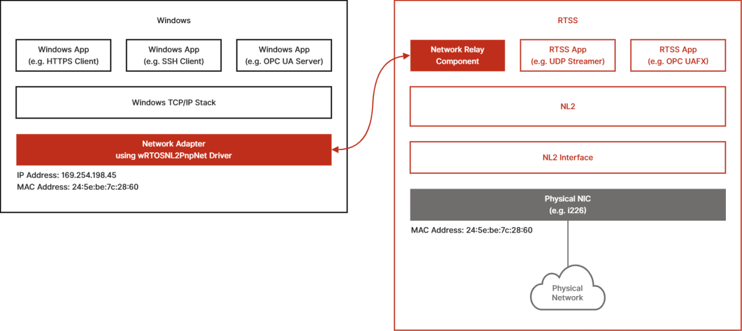
The diagram below illustrates the interactions between the different Windows and RTSS components. For simplicity, this example shows only one shared NIC, but multiple NICs may be shared in practice.
RTSS:
- An NL2 interface is defined and started. It has a MAC Address, which the NL2 NIC driver reads from the hardware. Several RTSS applications are running, and they all use the same NIC. One of these applications is the Network Relay component, which creates a communication channel with the Windows side.
Windows:
- The Network Adapter representing the shared NIC (an i226 in this example) is assigned the wRTOS NL2 plug-and-play net driver (wRTOSNL2PnpNet). This driver doesn’t access the hardware directly. Instead, it uses the communication channel created by the Network Relay component to exchange packets with the RTSS side. This mechanism is completely transparent to Windows applications. They send and receive packets through that network adapter as if it were controlled by Windows. Windows applications see the same MAC Address as the RTSS side and use an IP Address assigned by the Windows TCP/IP Stack (an automatically configured IP address in the example below).
Note: The wRTOSNL2PnpNet driver does not support line-based interrupts. A second driver, wRTOSPnpNet, is provided as a backup.
Typical Application Design Based on the Network Relay Feature
The main use case for the Network Relay feature is to relay all non-real-time traffic to and from Windows while processing real-time traffic on the RTSS side.
Typically, the transport layer used for real-time traffic is:
- UDP (real-time traffic is identified by specific UDP ports defined by the application)
- Other specific protocols that don’t use the IP EtherType (e.g. AVTP, cf. IEEE 1722)
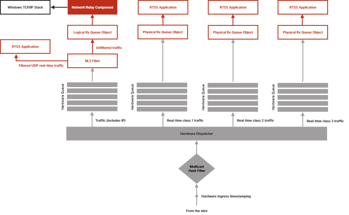
On receive, specific protocols can easily be forwarded to specific Receive Queues by the Hardware Dispatcher of the NIC (based on EtherType or Ethernet Priority tag). However, UDP real-time traffic cannot easily be separated from UDP non-real-time and TCP traffic. The diagram below shows how an application can take advantage of the Network Relay combined with an NL2 filter to extract the UDP real-time traffic and forward it to an RTSS application before it gets relayed to Windows:
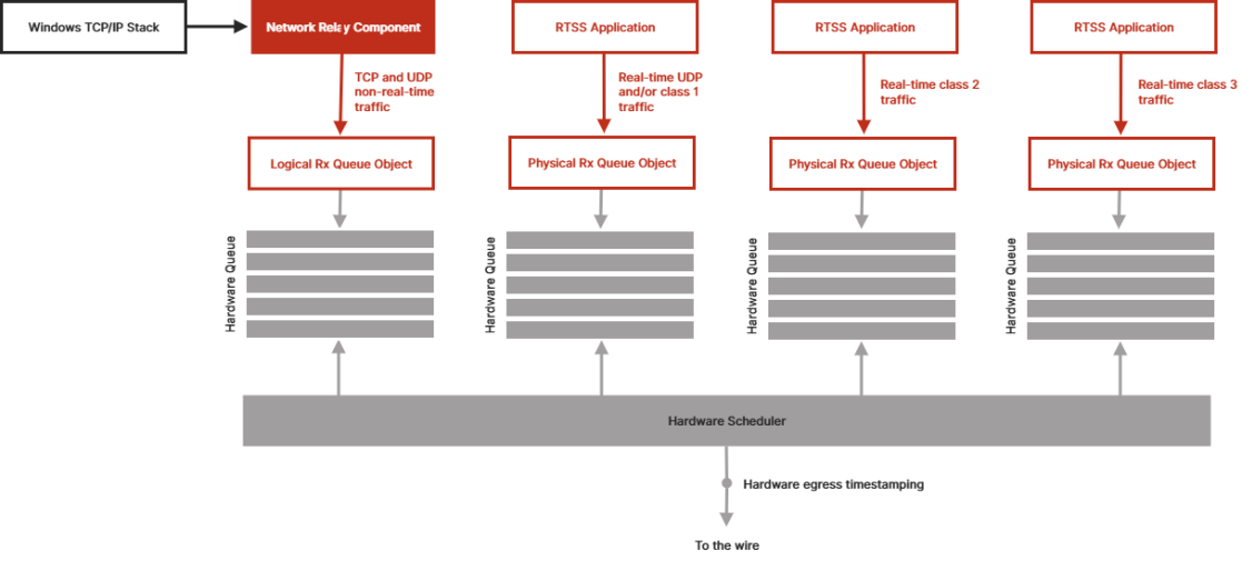
On transmit, the process is simpler, as the application knows which frames are part of the real-time traffic (UDP or specific protocols) and which are not, and it can determine the appropriate queue to use at send time.
Network Relay Component Behavior
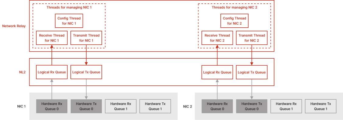
When the Network Relay component starts, it scans the list of NL2 interfaces to find those that have the Network Relay feature enabled. For each, it creates a Logical Receive Queue, a Logical Transmit Queue, and a set of 3 threads:
- Receive Thread: Waits for frames from the NIC and relays them to the Windows side.
- Transmit Thread: Waits for frames from the Windows side and relays them to the NIC. It also monitors the NIC's link status and relays any link status change information to the Windows side.
- Config Thread: Waits for configuration requests (multicast filtering, promiscuous mode, etc.) from the Windows side and configures the NIC accordingly.
The diagram below shows two NICs with the Network Relay feature enabled. In this example, each of them has two Hardware Receive Queues and two Hardware Transmit Queues. The Network Relay component uses Hardware Receive Queue 0 and Hardware Transmit Queue 0 on each NIC, so an RTSS application can use the other Receive or Transmit Hardware Queue to receive or send real-time traffic on the same NIC.
Configuration
On the RTSS Side
By default, the Network Relay feature is disabled on all NL2 interfaces. When the Network Relay component starts, it relays traffic only to or from NL2 interfaces that have Network Relay enabled.
For NL2 interfaces with Network Relay enabled, you can change the following settings:
- The index of the Hardware Receive/Transmit Queue used by the Logical Receive/Transmit Queue created by the Network Relay component to relay traffic from or to this interface. You can also change the buffer count used to create the Logical Receive/Transmit Queue
- The ideal processor and priority for each of the three management threads (see the previous section)
On the Windows Side
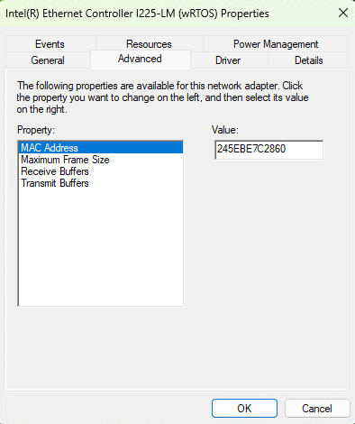
Any NIC converted to wRTOS is available to the Network Relay component. To convert a NIC to wRTOS, see Converting a Device from Windows to wRTOS. Once a NIC is converted to wRTOS, the following configuration parameters are accessible in the Windows Device Manager Properties dialog, under Advanced:
|
Parameter |
Meaning |
|---|---|
|
MAC Address |
The MAC Address of the NIC, as interpreted by Windows. This parameter is stored as 12 consecutive hex digits, which represent the 6 bytes of the MAC Address. This information cannot be retrieved automatically by Windows from the hardware because the hardware is fully controlled by RTSS. As a result, the MAC Address must be set manually through this parameter. If you don’t know the MAC Address of the NIC, do the following:
|
|
Maximum Frame Size |
The Maximum Frame Size that Windows is allowed to use on this NIC. The value is in bytes and includes the Ethernet header (14 bytes) but not the FCS (4 bytes) nor the potential VLAN tag (4 bytes). The default value is 1514. This information cannot be retrieved automatically and must be set manually. The Maximum Frame Size should be the same value as on the RTSS side:
|
|
Receive Buffers |
The maximum number of frames that can be simultaneously reported to Windows on receive. This information cannot be retrieved automatically and must be set manually. This should be set to the same value as the wRTOS interface’s Receive Buffer Count setting for the Network Relay component in wRTOS Settings. |
|
Transmit Buffers |
The maximum number of frames sent by Windows that can be buffered on transmit. This information cannot be retrieved automatically and must be set manually. This should be set to the same value as the wRTOS interface’s Transmit Buffer Count setting for the Network Relay component in wRTOS Settings. |
Note: Changes to one of the above parameters cause Windows to halt and re-initialize the NIC, which causes the NIC’s hardware resources to become momentarily unavailable to all CPU cores. This may cause disruptions in your RTSS application. To avoid this, do not change any parameter of a wRTOS-owned NIC while the Network Link Layer (NL2) is running.