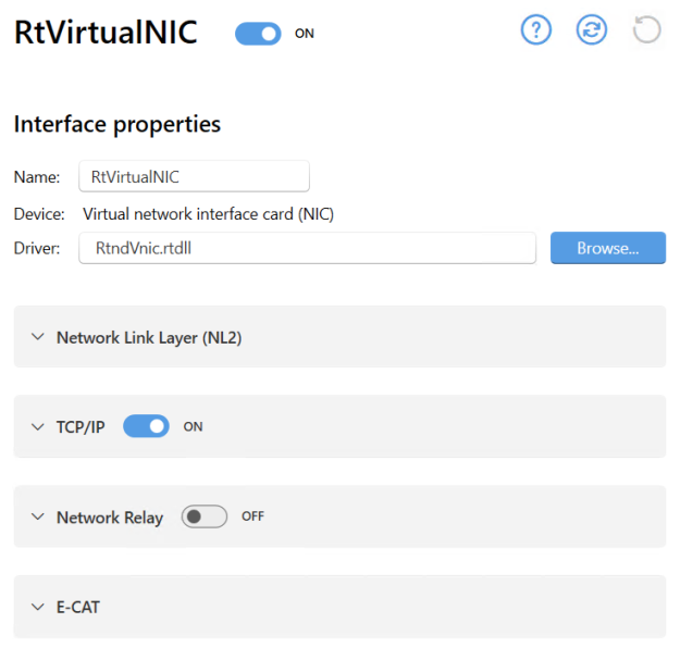
When a network interface is added on the Interfaces page in wRTOS Settings, a separate interface-specific page appears under Network / Interfaces / where you can configure that interface. On the interface-specific page, you can turn the interface on and off, control installed and licensed network components, and view or change settings specific to that interface.
When the wRTOS Virtual Network is installed with wRTOS Runtime, wRTOS Settings will contain a page called RtVirtualNIC at this location.
Note: Many network components require a separate product package and license. See wRTOS Platform Components for more information.
Note: A warning icon appears in the wRTOS Settings footer when a network component must be restarted to apply changes.
Note: Some settings require Windows Administrator privileges.
In this section:
- General Interface Settings
- Network Link Layer (NL2) Interface Settings
- Network Relay Interface Settings
- TCP/IP Interface Settings
- E-CAT Interface Settings
![]() Accessing Specific Network Interface Settings
Accessing Specific Network Interface Settings
General Interface Settings
The general interface settings listed below apply to all network interfaces, regardless of type.
Name
The unique name of the interface, as specified in the Add Interface dialog. See Adding an Interface for more information.
To change this setting:
Enter a new name in the text box. This name must be unique.
Device
The device associated with the interface, as specified in the Add Interface dialog. For example, Windows Virtual Ethernet Adapter (wRTOS). See Adding an Interface for more information. The device field is read-only.
Driver
The wRTOS driver for the supported NIC card.
To change this setting:
Do one of the following:
- Enter a driver file name (<filename>.rtdll) in the text box.
- Browse for a driver.
Controlling Network Component Interface Support
The interface-specific settings page contains a section for each installed and licensed wRTOS network component. In the section header for each component, you can turn that component's resources ON or OFF for the selected interface. Note that this is not available for the NL2, as NL2 resources must always be enabled.

To change a component's status:
Do one of the following:
- Set the toggle switch to ON (default) to enable component resources for the interface.
- Set the toggle switch to OFF to disable component resources for the interface.
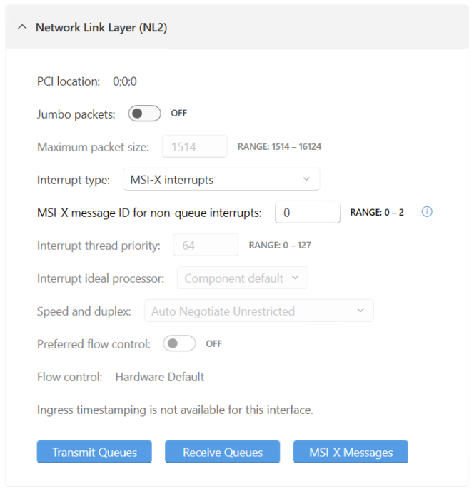
Network Link Layer (NL2) Interface Settings
Expand the Network Link Layer (NL2) section to display NL2-specific interface settings.
| Setting | Description | To change this setting |
|---|---|---|
| PCI location |
The PCI bus location of the network interface card for the interface, in the form of three semicolon-separated integers. For a physical NIC, this value specifies the location of the device in the PCI hierarchy (as it appears in the Windows Device Manager) and must not be 0;0;0. For non-physical PCI devices, like the Virtual NIC, this setting must be 0;0;0. Note: This field is read-only when wRTOS Settings can determine the Device Instance ID of the network interface. |
Enter a new value in the text field. |
|
Jumbo packets |
Determines whether the interface enables support for Jumbo packets. Jumbo allows to send and receive packets larger than the standard Ethernet size |
Do one of the following:
|
|
Maximum packet size |
The maximum packet size allowed by the interface. This includes the Ethernet header (14 bytes) but not the terminating Frame Check Sequence (4 bytes). The default value is 1514. The range of supported values is device specific. See Device Specific Interface Values for more information. Note: This setting is grayed out when Jumbo packets is set to OFF. |
Enter a new value in the text field. |
|
Interrupt type |
The interrupt type used by the interface. The default is NIC-dependent. These interrupt types are supported:
Note: For improved performance, we recommend using MSI-X when possible. |
Choose an interrupt type from the drop-down list. |
|
MSI-X message ID for non-queue interrupts |
The index of the MSI-X message for non-queue (Link Status Change and Egress Timestamping) interrupts. Note: The wRTOS Virtual NIC driver runs three threads: link status monitoring, receive, and transmit threads. When Line-Based or MSI is selected, all three threads run on the same processor at the same priority, similar to the IST of a physical NIC in Line-Based or MSI interrupt type. When MSI-X is selected, the processor and priority of each thread can be different and is set based on the MSI-X Message settings. Note: This setting is grayed out if Interrupt type is not set to MSI-X. |
Enter a new value in the text field. |
|
Interrupt thread priority |
The interrupt thread priority for the interface. This must be a valid wRTOS priority within the range of 0 to 127. Note: This setting is grayed out if Interrupt type is set to MSI-X. |
Enter a new value in the text field. |
|
Interrupt ideal processor |
The ideal processor for the thread servicing the interface interrupts. This value must be a valid RTSS processor. Component default uses the NL2’s default ideal processor value as configured on the Network Link Layer (NL2) page. Note: Processor numbers are zero-based. By default, the default RTSS processor is the ideal processor. Note: This setting is grayed out if Interrupt type is set to MSI-X. |
Choose a processor number from the drop-down list. |
|
Speed and duplex |
The method used to establish the Ethernet link:
The available options are device specific. See Device Specific Interface Values for more information. |
Choose an option from the drop-down list. |
|
Preferred flow control |
Determines whether the interface will use preferred flow control. When this is set to ON (default), you can choose a Flow control type (see below). |
Do one of the following:
|
|
Flow control |
Set the flow control type when Preferred flow control is set to ON:
Note: Not all devices support a preferred flow control. When preferred flow control is not supported, Hardware Default is selected. |
Choose an option from the drop-down list.
|
|
Hardware timestamping |
Determines whether hardware timestamping is globally enabled for the interface. Note: This setting will not appear when hardware timestamping is not available for the interface. Instead, this message will appear in its place: Hardware timestamping is not available for this interface |
Do one of the following:
|
|
Ingress timestamping |
The ingress timestamping rule used by the interface:
Note: This setting will not appear when hardware timestamping is not available for the interface. Instead, this message will appear in its place: Hardware timestamping is not available for this interface |
Choose an option from the drop-down list. |
|
Ingress timestamping EtherType |
The EtherType used to identify PTPv2 Ethernet events. The default value is device specific. Note: Not all NICs support changes to this value. Note: This option requires Ingress timestamping to be set to these values: • PTPv2 Ethernet Event Frames • PTPv2 UDP and Ethernet Event Frames Note: This setting will not appear when hardware timestamping is not available for the interface. Instead, this message will appear in its place: Hardware timestamping is not available for this interface |
Enter a value in hex notation in the text field. |
|
Ingress timestamping UDP Port |
The UDP port used to identify PTPv1/PTPv2 UDP events. The default value is device specific. Note: Not all NICs support changes to this value. Note: This option requires Ingress timestamping to be set to these values: • PTPv1 UDP Event Frames • PTPv2 UDP Event Frames • PTPv2 UDP and Ethernet Event Frames Note: This setting will not appear when hardware timestamping is not available for the interface. Instead, this message will appear in its place: Hardware timestamping is not available for this interface |
Enter a value in the text field. |
Transmit Queues
You can configure settings for individual transmit queues in the Transmit Queues dialog.
To configure transmit queues:
- Click Transmit Queues. The Transmit queues dialog appears.
- The available transmit queues are listed on the left of the dialog. Select a queue from the list to view or change its settings. Changes are applied immediately.
Transmit queue settings
These settings are available for each transmit queue.
Note: A transmit queue that is not enabled appears grayed-out in the list. To enable a transmit queue, find the queue in the list and set its toggle switch to ENABLED.
| Setting | Description | To change this setting |
|---|---|---|
| Queue status toggle |
Determines whether the queue is enabled or not enabled. Note: If a transmit queue will not be used by the user application, it should be disabled. Otherwise, it consumes system resources for no purpose. |
Do one of the following:
|
|
Buffer count |
The number of transmit buffers. When set to 0, wRTOS Settings uses the driver's default value. |
Enter a new value in the text field. |
|
MSI-X message ID |
The message ID associated with the transmit queue. This value must be within the range of 0 to the number of MSI-X messages - 1. This setting is grayed out if the interrupt type is not MSI-X. |
Enter a value in the text field or choose a value from the drop-down. |
|
Management thread priority |
The priority of the transmit queue's management thread. This must be a valid wRTOS priority within the range of 0 to 127. |
Enter a new value in the text field. |
|
Management ideal processor |
The ideal processor of this transmit queue's management thread. This value must be a valid RTSS processor. Component default uses the default NL2 ideal processor value as configured on the Network Link Layer (NL2) page. Note: Processor numbers are zero-based. By default, the default RTSS processor is the ideal processor. |
Enter a new value in the text field. |
|
Timestamping |
Determines whether timestamping is enabled for the selected transmit queue. Note: This can be set to ON only if the interface supports hardware timestamping and hardware timestamping is enabled at the interface level. |
Do one of the following:
|
|
Credit-based shaper |
Determines whether credit-based shaping is enabled for the selected transmit queue. Note: This setting will only be available if the interface supports credit-based shaping functionality. |
Do one of the following:
|
|
Launch time |
Determines whether launch time is enabled for the selected transmit queue. Note: This setting will only be available if the interface supports launch time functionality. |
Do one of the following:
|
Receive Queues
You can configure settings for individual receive queues in the Receive Queues dialog.
To configure receive queues:
- Click Receive Queues. The Receive queues dialog appears.
- The available receive queues are listed on the left of the dialog. Select a queue from the list to view or change its settings. Changes are applied immediately.
Receive queue settings
These settings are available for each receive queue.
Note: A receive queue that is not enabled appears grayed-out in the list (except for Queue 0, which is enabled and grayed-out by default). To enable a receive queue, find the queue in the list and set its toggle switch to ENABLED.
| Setting | Description | To change this setting |
|---|---|---|
| Queue status toggle |
Determines whether the queue is enabled or not enabled. Note: If a receive queue will not be used by the user application, it should be disabled. Otherwise, it consumes system resources for no purpose. |
Do one of the following:
|
|
Buffer count |
The number of receive queue buffers. When set to 0, wRTOS Settings uses the driver's default value. |
Enter a new value in the text field. |
|
MSI-X message ID |
The message ID associated with the receive queue. This value must be within the range of 0 to the number of MSI-X messages - 1. Note: This value is ignored when the interrupt type is Line-Based or MSI. |
Enter a value in the text box or choose a value from the drop-down. |
|
Management thread priority |
The priority of the receive queue's management thread. This must be a valid wRTOS priority within the range of 0 to 127. |
Enter a new value in the text field. |
|
Management ideal processor |
The ideal processor number for the receive queue's management thread. This value must be a valid RTSS processor. Component default uses the default NL2 ideal processor value as configured on the Network Link Layer (NL2) page. Note: Processor numbers are zero-based. By default, the default RTSS processor is the ideal processor. |
Enter a new value in the text field. |
|
Timestamping |
Determines whether timestamping is enabled for the selected receive queue. Note: This can be set to ON only if the interface supports hardware timestamping and hardware timestamping is enabled at the interface level. |
Do one of the following:
|
|
Filter driver |
Determines whether a filter driver will be used with the receive queue. Note: When a filter driver is associated with a receive queue, that queue cannot be used in exclusive mode. |
Do one of the following:
|
MSI-X Messages
You can configure settings for individual MSI-X messages in the MSI-X messages dialog.
To configure MSI-X messages:
- Click MSI-X Messages. The MSI-X messages dialog appears.
- The available messages are listed on the left of the dialog. Select a message from the list to view or change its settings. Changes are applied immediately.
MSI-X message settings
These settings are available for each MSI-X message.
| Setting | Description | To change this setting |
|---|---|---|
| Message status toggle |
Determines whether the message is enabled or not enabled. Note: If an MSI-X message is not associated with an interrupt cause (Transmit Queue, Receive Queue, or non-queue interrupt), it should be disabled. Otherwise, it consumes system resources for no purpose. |
Do one of the following:
|
|
Interrupt thread priority |
The priority for the IST (Interrupt Service Thread) associated with this MSI-X message. This must be a valid wRTOS priority within the range of 0 to 127. |
Enter a new value in the text field. |
|
Interrupt ideal processor |
The ideal processor for the IST (Interrupt Service Thread) associated with this MSI-X message. This value must be a valid RTSS processor. Component default uses the default NL2 ideal processor value as configured on the Network Link Layer (NL2) page. Note: Processor numbers are zero-based. By default, the first RTSS processor is the ideal processor. |
Enter a new value in the text field. |
Network Relay Interface Settings
Expand the Network Relay section to display Network-Relay-specific interface settings. In this section, you can turn Network Relay functionality on and off for the interface and view and configure settings.
| Setting | Description | To change this setting |
|---|---|---|
|
Receive buffer count |
The number of buffers to allocate for the Logical Receive Queue used by the Network Relay component for this interface. The default value is 512. |
Enter a new value in the text field. |
|
Receive queue index |
The index of the Receive Queue used by the Network Relay component for this interface. This index must correspond to an enabled Receive Queue of the interface. The default value is 0. |
Enter a new value in the text field. |
|
Receive ideal processor |
The ideal processor for the receive thread. This value must be a valid RTSS processor. Component default uses the default Network Relay ideal processor value as configured on the Network Relay page. Note: Processor numbers are zero-based. By default, the first RTSS processor is the ideal processor. |
Choose a processor number from the drop-down list. |
|
Receive thread priority |
The receive thread priority for the interface. This must be a valid wRTOS priority within the range of 0 to 127. |
Enter a new value in the text field. |
|
Transmit buffer count |
The number of buffers to allocate for the Logical Transmit Queue used by the Network Relay component for this interface. The default value is 512. |
Enter a new value in the text field. |
|
Transmit queue index |
The index of the Transmit Queue used by the Network Relay component for this interface. This index must correspond to an enabled Transmit Queue of the interface. The default value is 0. |
Enter a new value in the text field. |
|
Transmit ideal processor |
The ideal processor for the transmit thread. This value must be a valid RTSS processor. Component default uses the default Network Relayideal processor value as configured on the Network Relay page. Note: Processor numbers are zero-based. By default, the first RTSS processor is the ideal processor. |
Choose a processor number from the drop-down list. |
|
Transmit thread priority |
The transmit thread priority for the interface. This must be a valid wRTOS priority within the range of 0 to 127. |
Enter a new value in the text field. |
|
Config ideal processor |
The ideal processor for the config status thread. This value must be a valid RTSS processor. Component default uses the default Network Relay ideal processor value as configured on the Network Relay page. Note: Processor numbers are zero-based. By default, the first RTSS processor is the ideal processor. |
Choose an option from the drop-down. |
|
Config thread priority |
The config status thread priority for the interface. This must be a valid wRTOS priority within the range of 0 to 127. |
Enter a new value in the text field. |
TCP/IP Interface Settings
Expand the TCP/IP section to display TCP/IP-specific interface settings. In this section, you can turn TCP/IP functionality on and off for the interface, control the TCP/IP component, and view and configure settings.
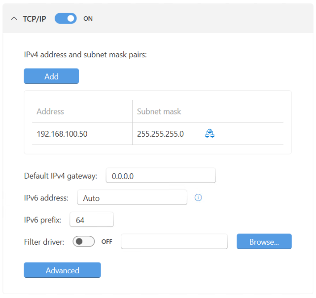
The first time you enable TCP/IP functionality for an interface, the Add IPv4 configuration dialog appears, through which you can create a new IPv4 address and subnet mask pair. See Configuring IPv4 Address and Subnet Mask Pairs below.
| Setting | Description | To change this setting |
|---|---|---|
| IPv4 address and subnet mask pairs | Add up to 12 IPv4 address and subnet mask pairs in dotted quad notation. | |
| Default IPv4 gateway |
The IPv4 gateway for this interface. If this value is not specified, the interface has no gateway. This setting is optional. Note: This value must be a valid IP address in dotted quad notation. Leading zeroes are not supported. |
Enter a valid IP address in the text box. |
| IPv6 address |
The IPv6 address. By default, the interface's automatic IPv6 link-local address is used. Optionally, you can specify an IPv6 address to use in addition to the automatic address. |
Enter an additional IPv6 address in the text box. |
| IPv6 prefix |
The IPv6 network prefix. The default value is 64. |
Enter a new value in the text field. |
|
Filter driver |
The path and name of the filter driver associated with the interface. Hover over the text field to display the full path. Note: You can only create one filter per interface. |
To change the filter driver’s status:
To choose a filter driver, do one of the following:
|
Configuring IPv4 Address and Subnet Mask Pairs
Under TCP/IP, you can add up to 12 IPv4 address and subnet mask pairs.
To add an IPv4 address and subnet mask pair:
- Click Add. The Add IPv4 configuration dialog appears.
- Enter an Address and Subnet mask in dotted-quad notation.
- Click OK. The new IPv4 address and subnet mask pair is added to the list.
To edit an IPv4 address and subnet mask pair:
- Find the address and subnet mask pair you want to remove.
- Click Edit. The Edit IPv4 configuration dialog appears.
- Enter an Address and Subnet mask in dotted-quad notation.
- Click OK.
To remove an IPv4 address and subnet mask pair:
- Find the address and subnet mask pair you want to remove.
- Click Delete.
Advanced TCP/IP interface settings
You can configure advanced TCP/IP interface settings in the Advanced TCP/IP settings dialog.
To configure advanced TCP/IP interface settings:
- Click Advanced. The Advanced TCP/IP settings dialog appears.
- Configure the available settings. Changes are applied immediately.
| Setting | Description | To change this setting |
|---|---|---|
|
Link status monitoring |
Determines whether link status monitoring is enabled for the interface. |
Do one of the following:
|
|
Link status ideal processor |
The ideal processor for the link status thread. This value must be a valid RTSS processor. Component default uses the default TCP/IP ideal processor value as configured on the TCP/IP page. Note: Processor numbers are zero-based. By default, the first RTSS processor is the ideal processor. |
Choose an option from the drop-down. |
|
Link status priority |
The link status thread priority for the interface. This must be a valid wRTOS priority within the range of 0 to 127. |
Enter a new value in the text field. |
|
Receive thread priority |
The receive thread priority for the interface. This must be a valid wRTOS priority within the range of 0 to 127. |
Enter a new value in the text field. |
|
Receive ideal processor |
The ideal processor for the receive thread. This value must be a valid RTSS processor. Component default uses the default TCP/IP ideal processor value as configured on the TCP/IP page. Note: Processor numbers are zero-based. By default, the first RTSS processor is the ideal processor. |
Choose a processor number from the drop-down list. |
|
Receive buffer count |
The number of buffers to allocate for the Logical Receive Queue used by the TCP/IP component for this interface. The default value is 512. |
Enter a new value in the text field. |
|
Receive queue index |
The index of the Receive Queue used by the TCP/IP component for this interface. This index must correspond to an enabled Receive Queue of the interface. The default value is 0. |
Enter a new value in the text field. |
|
Transmit buffer count |
The number of buffers to allocate for the Logical Transmit Queue used by the TCP/IP component for this interface. The default value is 512. |
Enter a new value in the text field. |
|
Transmit queue index |
The index of the Transmit Queue used by the TCP/IP component for this interface. This index must correspond to an enabled Transmit Queue of the interface. The default value is 0. |
Enter a new value in the text field. |
E-CAT Interface Settings
E-CAT Settings
| Setting | Description | To change this setting |
|---|---|---|
| MainDevice instance |
The MainDevice instance for the network interface card, as configured on the E-CAT page. This value combines the MainDevice instance number and name in the format Number: Name. For example: 0: XY Panel Control Note: Instances with a value greater than 0 (Default) require a Multiple MainDevice license. |
|
| Role |
The network interface card role, as configured on the E-CAT page. The role can be one of two options:
Note: Secondary NICs require a Cable Redundancy license. |
RELATED Topics: