In this
- Overview
- Exported APIs
- Network Link Layer (NL2) Communication
- Buffer Management System and Memory Requirements
- Virtual Network
- Ethernet Filter Driver
- Loopback
Overview
The wRTOS TCP/IP Stack implements the Network and Transport layers of the OSI model as shown below:
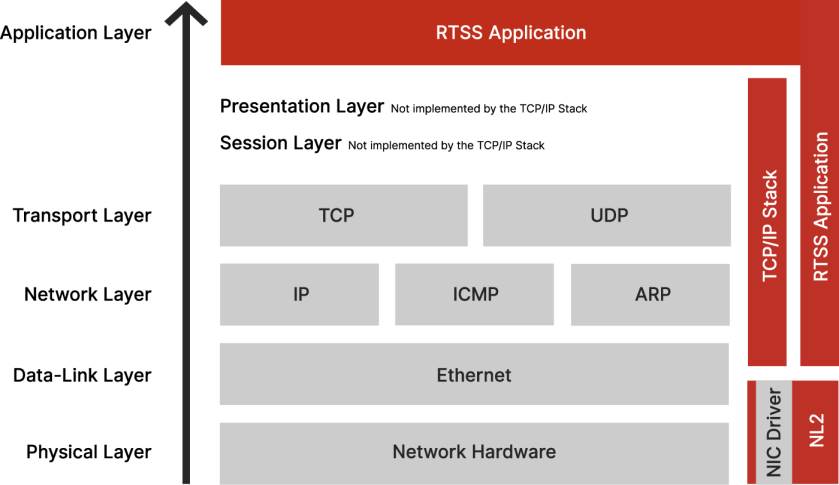
The TCP/IP Stack runs in an RTSS process that relies on the Network Link Layer (NL2) to send and receive Ethernet packets on the network.
You can configure the TCP/IP Stack in wRTOS Settings.
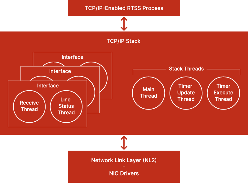
The TCP/IP Stack process runs the following threads:
- For each interface:
- One Receive thread, responsible for processing incoming packets
- One (sometimes none) Line Status thread. The Line Status thread is spawned only if Line Status Monitoring is enabled for this interface. This thread is responsible for monitoring the NIC’s link status and reinitializing TCP/IP on the interface whenever the link gets brought up again.
- For the Stack as a whole:
- One Main thread, responsible for starting and stopping the Stack.
- One Timer Update thread, responsible for maintaining the Stack’s internal tick count.
- One Timer Execute thread, responsible for processing all Stack timers (e.g. TCP retransmission timer, IP reassembly timer, ARP timeout, etc.).
Notes
- Packet send operations are performed either within the context of the TCP/IP-enabled RTSS Process or within the context of the Timer Execute thread.
- The Timer Update and the Timer Execute always run on the same Core.
Exported APIs
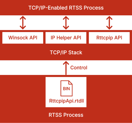
The TCP/IP Stack exports three API sets to TCP/IP-Enabled RTSS Processes:
- The Winsock API set mimics the Microsoft Winsock API.
- The IP Helper API set mimics the Microsoft IP Helper API.
- The Rttcpip API set provides miscellaneous wRTOS-specific functions to interact further with the TCP/IP Stack.
In addition to the APIs exported by the TCP/IP Stack, RTSS Processes that link with RttcpipApi.rtdll, whether they link with the Stack itself or not, get a different set of APIs to control the TCP/IP Stack (start, stop, get running status and get licensing status).
Network Link Layer (NL2) Communication
The TCP/IP Stack uses the NL2’s shared queue method to send and receive packets. It does not take exclusive control of any hardware queue. This allows other NL2 applications to send and receive through the same queues as the TCP/IP Stack. This is especially useful when the network interface has only one transmit and one receive queue. By default, the Stack uses the first Transmit Queue and the first Receive Queue of each interface.
Buffer Management System and Memory Requirement
The TCP/IP Stack has an internal buffer system that statically allocates a fixed memory block during Stack startup for performance reasons. This memory block, specified by the Memory allocated for the TCP/IP Stack heap setting configured in wRTOS Settings, stores the Stack’s internal information, such as packet buffers and various control information. The Stack’s packet buffers operate independently of NL2 buffers. During send and receive operations, they copy data from/to the Stack buffers to/from the NL2 buffers.
The Stack’s memory requirements vary based on the amount of memory available on the system and the expected level of network traffic. Key factors influencing this requirement include:
- The size of your socket queue
- The size of application buffers for transfer
- The number of sockets
- The number of network interfaces
- The number of pre-allocated receive buffers for the device
Most of the memory pre-allocated by the Stack is used for application data. Internally, the TCP/IP Stack uses minimal data.
If you are unsure how much memory should be allocated for the Stack, use a large value, such as 10,000. Fatal errors can occur when not enough memory is allocated to the TCP/IP Stack. The TCP/IP Stack will return WSAENOBUFS to an application when memory reserves have been exhausted. This indicates that they should increase this value.
Virtual Network
The wRTOS Virtual Network is a virtual point-to-point connection between Windows and wRTOS. The network interface to this virtual network on the Windows side is called the Windows Virtual wRTOS Ethernet Adapter. The network interface to this virtual network on the wRTOS side is referred to as the wRTOS Virtual Network Interface (NIC). The Stack can take advantage of the virtual network to provide socket-based communication between a Windows application and a wRTOS application.
The wRTOS Virtual NIC is provided by default if you install the Virtual Network feature. It sets up a default IP address and is associated with the RtndVnic.rtdll NL2 driver. The wRTOS Virtual NIC driver represents the RTSS component of the point-to-point Virtual Network connection.
The Windows Virtual wRTOS Ethernet Adapter is associated with the NL2 plug-and-play NDIS driver (wRTOSNL2PnpNet.sys) loaded by the Windows Stack.
Related topics:
Ethernet Filter Driver
Each TCP/IP-enabled interface can be associated with an Ethernet Filter Driver. A filter driver intercepts all incoming and outgoing frames and can modify them on the fly. It can also generate new network traffic.
Loopback
The Loopback interface provides a socket-based communication feature between two wRTOS applications. The TCP/IP Stack entirely manages the Loopback interface; the traffic sent and received remains inside the Stack, it doesn’t go through the NL2. This must not be confused with the Virtual NIC, which connects a wRTOS application with a Windows application and utilizes the NL2. For more information on this feature, see the Multicast sample.