This section provides information about the E-CAT ESI Import Tool user interface.
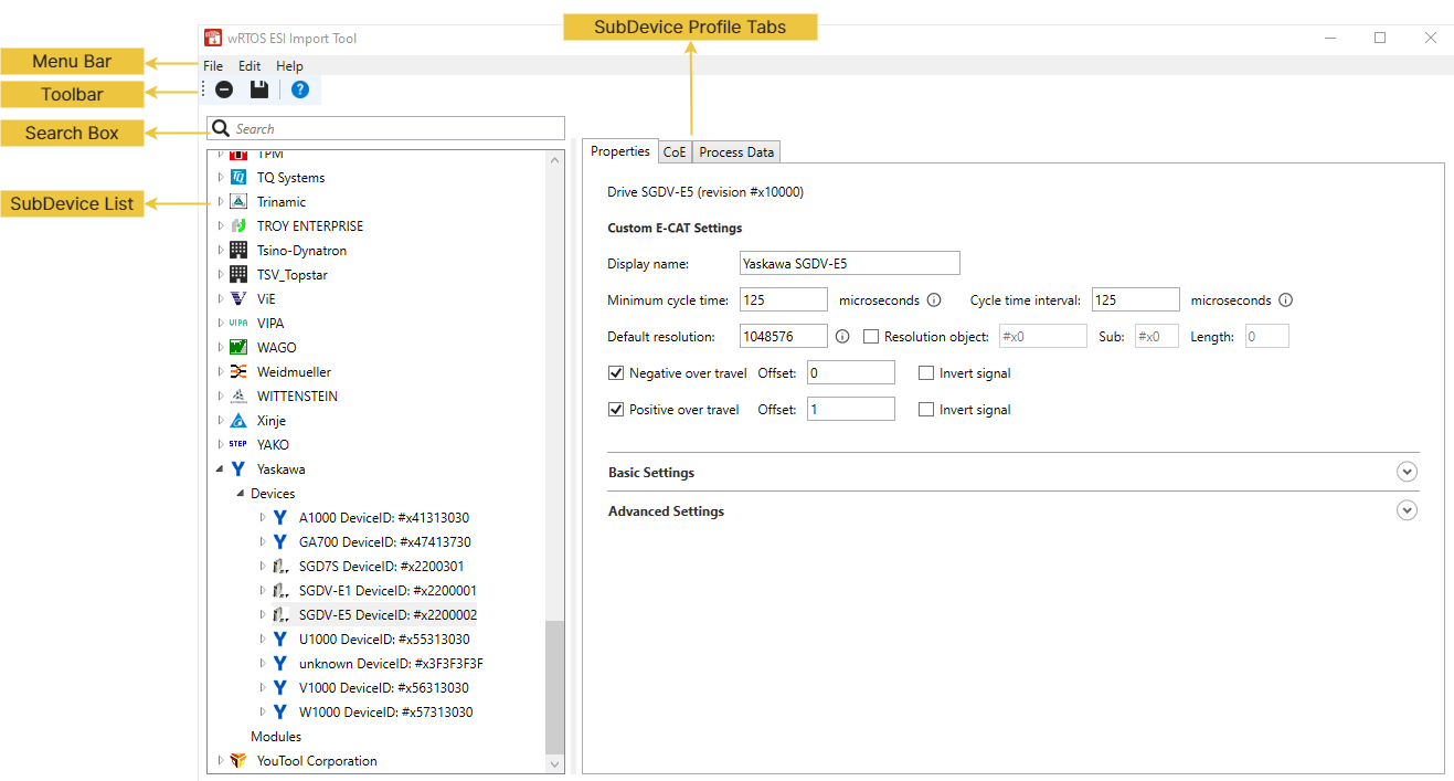
Menu Bar
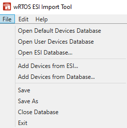
You can use the functions in the Menu Bar to process ESI data. There are three menus: File, Edit, and Help.
| Menu name | Description |
|---|---|
|
|
This tool provides three methods to open a database:
Note: Modification in the Default Devices Database is not allowed. If you want to modify the device's ESI data in the default database, import the data to User Devices Database and modify it from there. Note: You can use the default database to view device details of all supported EtherCAT devices or use it as a base to edit or add the desired devices. Remember to save the modified database to a different location by choosing File > Save As. You can open this edited database later using Open ESI Database.
After creating the database, you can add ESI files to the database. To add one or more ESI files to this database, choose File > Add Devices from ESI to ESI files in .xml format provided by the hardware manufacturers, or choose File > Add Devices from Database to add files from existing database. Finally, select the Note: The User Devices Database has the highest priority. If both the Default Devices Database and User Devices Database contain data for the same device, the tool will use settings from the User Devices Database. Note: To improve the E-CAT connection loading speed, you can store the ESI data for all devices connected to the E-CAT component in the User Devices Database. Once the E-CAT component finds the ESI data of all devices in the User Devices Database, it will skip reading the same ESI data from the Default Devices Database.
After opening a database, you can use these methods to add more devices to the database:
After making changes to the database, you can use these functions to save or close the database.
|
|
|
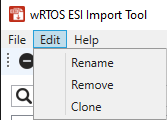
You can use these functions to edit devices/modules in the SubDevice List.
The Clone function is only valid if:
Note: You can also perform these functions by right-clicking a device/module in the SubDevice List. See SubDevice List. |
|
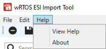
Help Menu
|
|
Toolbar
Function icons on the Toolbar:
| Icon | Name | Action |
|---|---|---|
|
|
Remove selected device or module |
Select a device/module in the SubDevice List, then choose this icon to remove it from the list. |
|
|
Save changes to the database |
After editing a database, choose this icon to save changes to the current database. |
|
|
View documentation |
Choose this icon to display the E-CAT ESI Import Tool online Help. |
Search Box
The Search Box can find devices/modules in the SubDevice List. To do this, enter a device/module property in the Search Box, such as a vendor name, device/module name, or revision number, and then press Enter. The list will filter and display devices/modules matching the criteria. To display the entire list, clear the Search Box and press Enter.
SubDevice List
Once a database is selected, its devices/modules are shown in the SubDevice List.
The devices/modules are sorted by company name. You can expand a company to view its devices/modules or expand a device/module to see its revision number.
Select a device/module, its profile is displayed in the SubDevice Profile Tabs in the right pane.
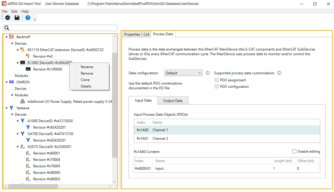
You can right-click a device/module to perform the Rename, Remove, Clone, or show Details functions. See Edit Menu for more details.
SubDevice Profile Tabs
Select a device/module from the SubDevice List to view its profile in the Properties, CoE, and Process Data tabs.
Properties
Select a device/module from the SubDevice List, then select the Properties tab. You can view device profile read from the ESI file.
Note: The content in Properties varies depending on the selected SubDevice type, e.g. drive, I/O, or module.
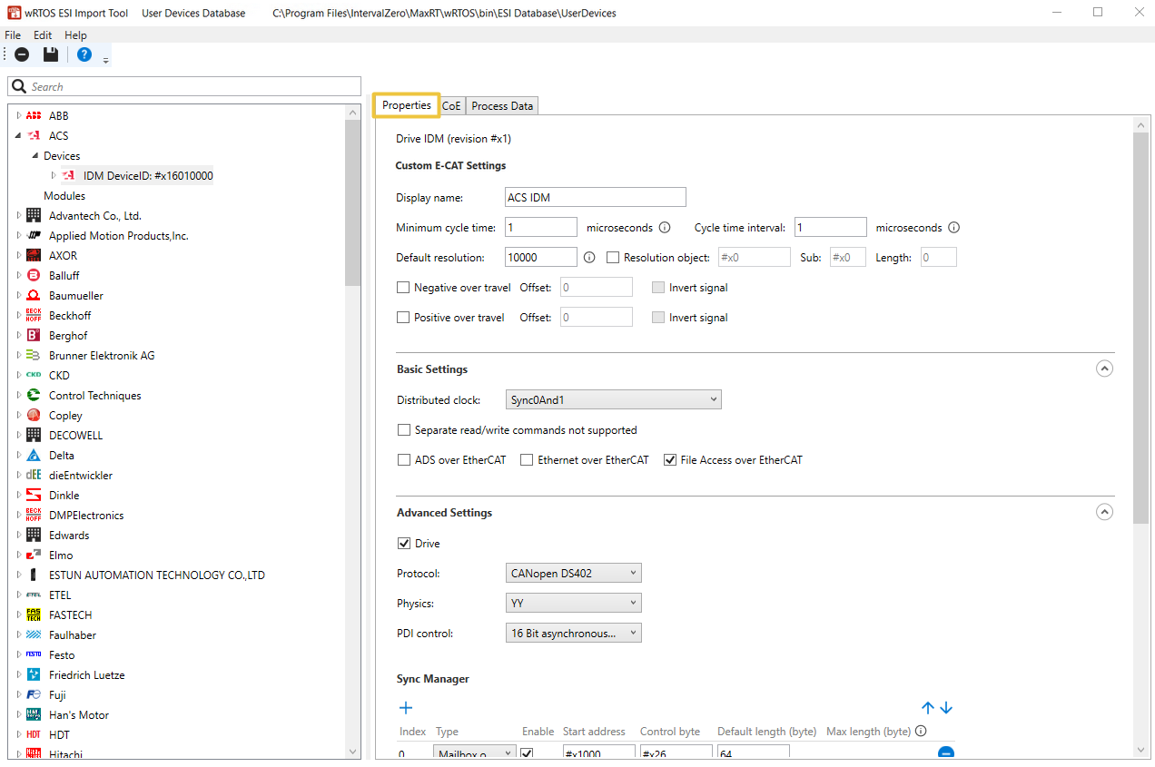
Custom E-CAT Settings
This field contains essential device information for the E-CAT component, though it's not included in the ESI file. When importing an ESI file, the tool provides default values for these settings, which you should adjust to match your specific SubDevice.
Note: The content varies depending on the selected SubDevice type, e.g. drive, I/O, or module.
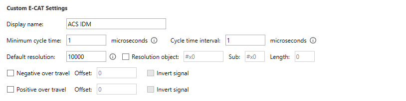
- Display name: The SubDevice's name used by the E-CAT component. The value is valid between 1-64 characters.
- Minimum cycle time: The minimum cycle time the device can accept. The default value is 1000 microseconds. The value must be between 1 and 1,000 microseconds. For more information about the cycle time of your device, see the device's manual.
- Cycle time interval: The interval between cycle times. The default value is 1000 microseconds. Some device may only support specific cycle time intervals, such as 125, 250, 500. The value must be between 1 and 1,000 microseconds.
- Default Resolution: The default resolution of the encoder. This must be set according to the drive's manual.
- Resolution object: Check this box if you want the E-CAT component to read a specified resolution from the drive's Service Data Object (SDO) rather than the value setup in this field. Please ensure the drive has an SDO object with the resolution. Input the index of the resolution object in the box.
- Sub: Input the subindex of the resolution object.
- Length: Input the length of the resolution object.
- Resolution object: Check this box if you want the E-CAT component to read a specified resolution from the drive's Service Data Object (SDO) rather than the value setup in this field. Please ensure the drive has an SDO object with the resolution. Input the index of the resolution object in the box.
- Negative over travel: Check the box to enable the Negative over Travel function if the drive supports it. This function is a homing method defined in the DS402 standard, specifying a drive to move in the negative direction.
- Offset: The bit offset of a drive's digital input. According to DS402, bit 0 should be negative overtravel.
- Invert signal: Check the box to invert the Offset value.
- Positive over travel: Check the box to enable the Positive over Travel function if the drive supports it. This function is a homing method defined in the DS402 standard, specifying a drive to move in the positive direction.
- Offset: The bit offset of a drive's digital input. According to DS402, bit 1 should be positive overtravel.
- Invert signal: Check the box to invert the Offset value.
Basic Settings
These settings are only available for devices (drives and I/Os).
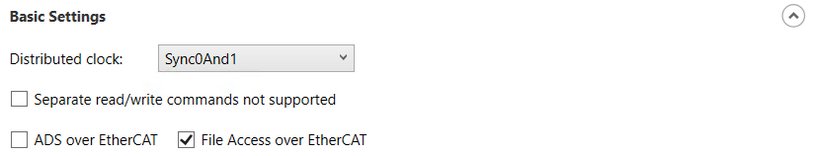
- Distributed clock: Select a distributed clock option.
- None: No clock.
- Sync0: Select to use the Sync0 signal.
- Sync1: Select to use the Sync1 signal.
- Sync0And1: Select to use the Sync0 and Syn1 signals.
- Separate read/write commands not supported: Check the box if the device doesn't accept separate logical read/write commands (LRD and LWR). It only accepts combined logical read/write command (LRW).
- ADS over EtherCAT (AoE): Check the box if this device supports AoE.
- File Access over EtherCAT (FoE): Check the box if this device supports FoE.
Advanced Settings
Configure the advanced settings for a drive or module.
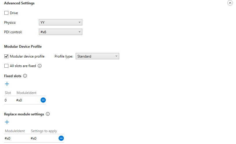
- Drive: Check the box if this device is a drive.
- Protocol: This option is only available when Drive is checked. Select a motion protocol used by this drive. Options include None, CANopen DS402, MDP741, Sercos over EtherCAT, and Beckhoff KBus.
- Physics: Physic type of each port.
- The 1st character: Physics of logical port 0.
- The 2nd character: Physics of logical port 1.
- The 3rd character: Physics of logical port 2.
- The 4th character: Physics of logical port 3.
- Allowed values:
- Y: MII
- H: MII - Fast Hot Connect
- K: E-Bus (LVDS)
- (Empty): This port is not used (blank character)
- The value should contain but not limit to: YY, YKY, KK, and (empty)
- PDI control: Select a Process Data Interface (PDI) control option. The PDI control defines how the EtherCAT chip connects to the EtherCAT SubDevice's application.
- Modular Device Profile: Check the box if this is a modular device, such as a gateway.
- Profile type: Select a profile type.
- All slots are fixed: Check the box if all slots of the modular device are specified by the below Fixed slots table.
- Fixed slots: Use the
 Add icon to add a slot and specify a ModuleIdent identifier for this slot. The E-CAT component will not scan these slots when connecting to SubDevices.
 - Replace module settings: Use the Add icon to add a ModuleIdent specified above and apply a value to it.
- Fixed slots: Use the
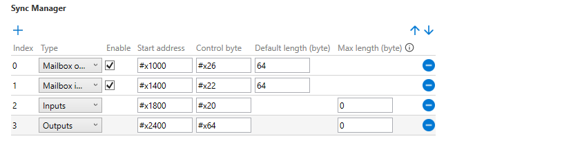
Sync Manager
This field is only available to devices (drives and I/Os). The Sync Manager ensures that the EtherCAT MainDevice and SubDevice's access to the data in Dual-Port RAM (DPRAM) is synchronized. You can adjust the synchronization settings in the corresponding fields.
- Index: The index of the Sync Manager. The indexes are sorted in ascending order. You can use the
 Move up or
  Move down icons to adjust the order. To add more indexes, use the Add icon. To delete an index, use the
  Delete icon.
- Type: Select a data transmission type for the Sync Manager.
- Mailbox output: Transmit mailbox data from the MainDevice to the SubDevice. Check the Enable box to activate Sync Manager's memory control. Uncheck the Enable box to disable Sync Manager's memory control.
- Mailbox input: Transmit mailbox data from the SubDevice to the MainDevice. Check the Enable box to activate Sync Manager's memory control. Uncheck the Enable box to disable Sync Manager's memory protection.
- Outputs: Transmit process data from the MainDevice to the SubDevice. The E-CAT component automatically determines the Sync Manager's memory control for this data.
- Inputs: Transmit process data from the SubDevice to the MainDevice. The E-CAT component automatically determines the Sync Manager's memory control for this data.
- Start address: The physical start address of the Sync Manager.
- Control byte: The Sync Manager control byte.
- Default length (byte): The Sync Manager's default size in bytes. The valid value is between 1-10000. This setting is only applicable to Mailbox output and Mailbox input.
- Max length (byte): The maximum Sync Manager length, in bytes, supported by the SubDevice. The valid value is between 0-10000. This setting is only applicable to Outputs and Inputs.
Fieldbus Memory Management Unit (FMMU)
This field is only available for devices (drives and I/Os).
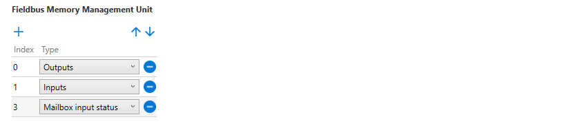
- Index: The Fieldbus Memory Management Unit (FMMU) index. The indexes are sorted in ascending order. You can use the Move up or Move down icons to adjust the order. To add more indexes, use the Add icon. To delete an index, use the Delete icon.
- Type: Select an FMMU usage type.
- Outputs: The FMMU is used for output Process Data Object (PDO).
- Inputs: The FMMU is used for input Process Data Object (PDO).
- Mailbox input status: The FMMU maps the Write Event Flag of the Input Mailbox (register 0x080D.0) to the process data. This allows the MainDevice to avoid polling the Input Mailbox when waiting for a Mailbox Response, which is highly recommended to reduce traffic.
CoE
Select a device/module from the SubDevice List, and then select the CoE tab. You can modify CANopen over EtherCAT (CoE) properties and the SDO objects in the Custom Initialization Commands table.
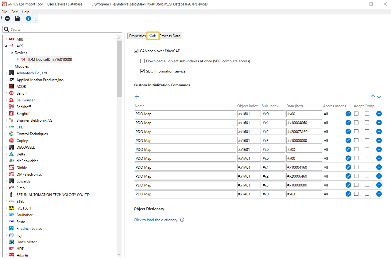
- CANopen over EtherCAT (CoE): Check the box to enable CoE. Ensure the SubDevice supports CoE.
- When the box is checked, you can further configure the following settings.
- When the box is unchecked:
- The following settings will be disabled.
- The PDO configuration and PDO assignment options in the Process Data tab will be unchecked and disabled.
- Data in the Custom Initialization Commands field will be cleared and disabled.
- Download all object sub-indexes at once (SDO complete access): This setting is only available when CANopen over EtherCAT is checked. Check the box to activate uploading/downloading the complete SDO object, if supported by the device. This will read or write the entire data for the main index and all its sub-indexes.
- SDO information service: This setting is only available when CANopen over EtherCAT is checked. Check the box if the MainDevice can read the object dictionary from the SubDevice.
- Custom Initialization Commands: This is an initialization command list for a device. These commands are executed based on the order in the table each time the MainDevice connects to the SubDevice. You can manually add or modify the commands. To adjust the order, use the Move up or Move down icons. To add a new command, use the Add icon. To delete a command, use the Delete icon.
- Name: The command name.
- Object index: The object index.
- Sub-index: The object sub-index.
- Depend on slot: This command is only available for modules. Check the box if the command index should be changed dynamically based on the module's slot number and the device's index increment.
- Data (hex): The object data.
- Access modes: This command is only available for devices. The access modes to execute this command. To change the access modes, use the
 Edit icon. Select Always download all (default) to use all access modes or select the desired access modes to execute this command.
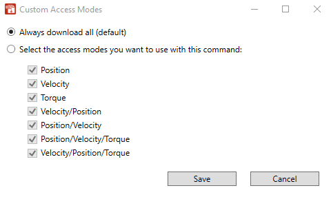
- Adapt: Check the box to overwrite the Data specified in the command with the actual value from an object. The Data value will be adapted to the cycle time of the EtherCAT MainDevice.
- Comp: Check the box to enable SDO complete access for this command.
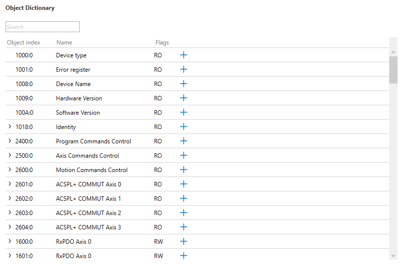
- Object Dictionary: This field is only available for devices. After selecting the Click to load the dictionary button, the content of the object dictionary will be displayed. If the device has no object dictionary, the content will be empty. You can use the Add icon to add the desired items to the Custom Initialization Commands field.
-
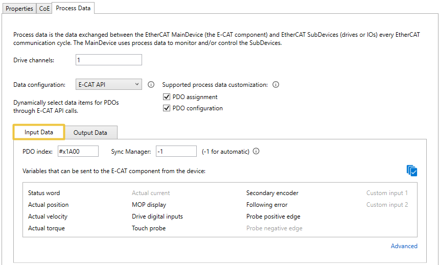
Process Data
Select a device/module from the SubDevice List, and then select the Process Data tab. The Process Data Object (PDO) is a type of periodic data object that can be used to exchange data between an EtherCAT MainDevice (the E-CAT Component) and EtherCAT SubDevices (drives or I/Os) during each EtherCAT communication cycle, typically every 1 millisecond. The MainDevice can monitor and control the SubDevices through process data exchange.
Note: The content varies depending on the selected SubDevice type, e.g. device (drive and I/O), or module.
If a module is selected:
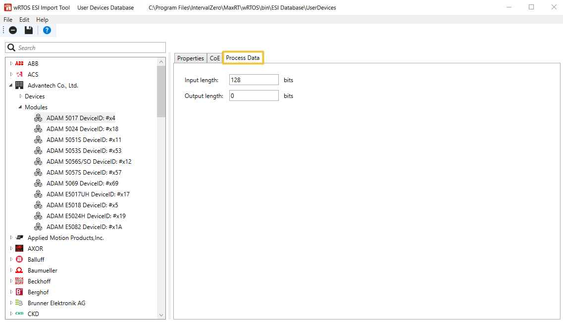
- Input length: The total input PDOs length of this module.
- Output length: The total output PDOs length of this module.
If a device (drive or I/O) is selected:
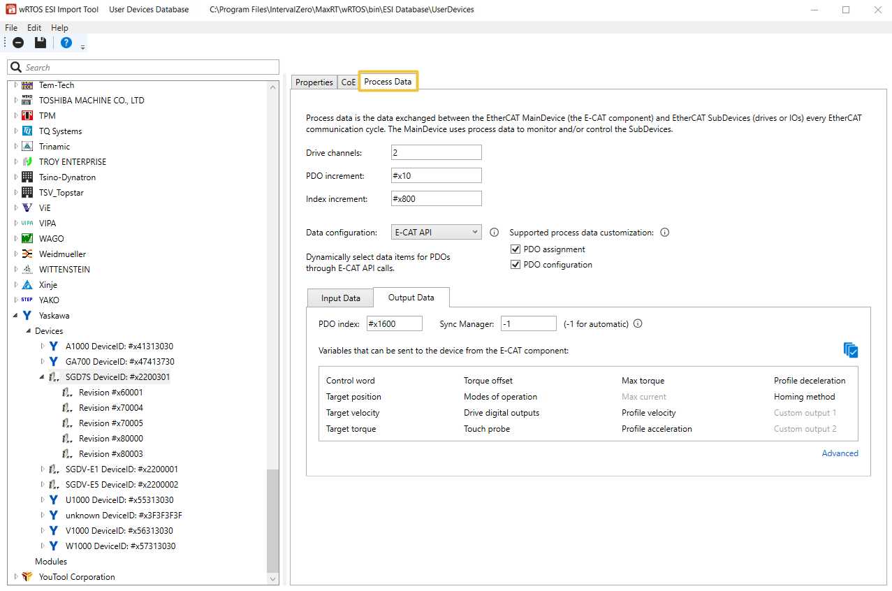
- Drive channels: The axis count of the drive. The value is valid between 1-10000.
- PDO increment: This option is only available when Drive channels is greater than 1. This is the PDO index increment for channels. For example, if the first PDO of channel 1 is #x1600 and the PDO increment is #x10, then the first PDO of channel 2 is #x1610.
- Index increment: This option is only available when Drive channels is greater than 1. This is the dictionary object index increment for channels. For example, if the control word index of channel 1 is #x6040 and the index increment is #x800, then the control word index of channel 2 is #x6840.
- Data configuration: Select a process data configuration mode for devices to exchange process data. There are four modes: Default, Manual, Access Mode, and E-CAT API.
- Default: Use the default PDO combinations specified in the device's ESI file for process data exchange.
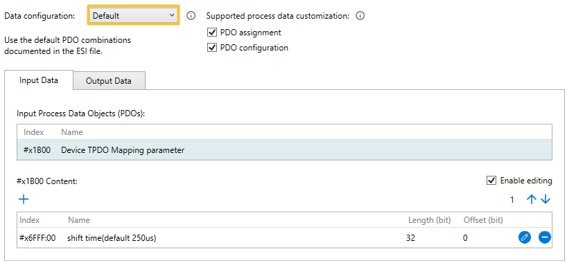
- Setup steps: Select Default from the Data configuration drop-down menu, the supported PDOs and the corresponding variables (PDO entries) will be displayed in the Input Data and Output Data fields. The device will use these default PDO combinations for process data exchange.
- Manual: You can select the PDOs and the corresponding variables (PDO entries) for process data exchange. The variables that can be selected depend on the attributes of the PDOs, as well as the device's supported PDO assignment and PDO configuration.
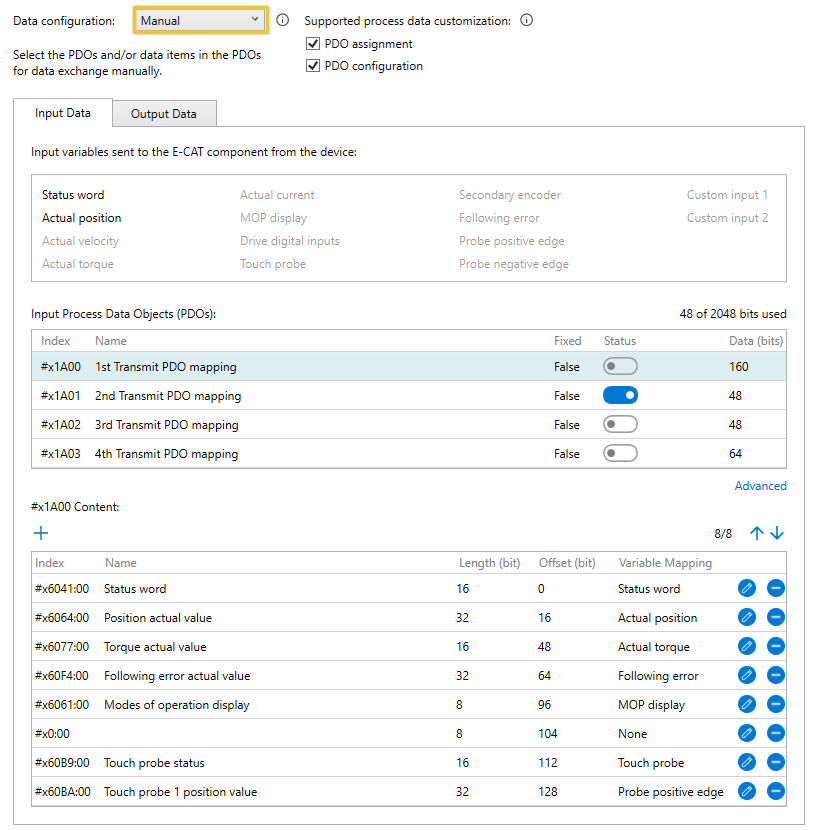
- Criteria for choosing this type: The devices should support the PDO assignment or PDO configuration.
- Setup steps:
- Select Manual from the Data configuration drop-down menu, the tool will automatically detect and display the supported PDOs and the corresponding variables (PDO entries) of the device in the Input Data and Output Data fields.
- In the Input Process Data Objects or Output Process Data Objects field, toggle the Status switch to enable or disable the desired PDOs for process data exchange. Its variables will be displayed in the below area. To add more variables, use the Add icon. To delete a variable, use the Delete icon. To edit a variable, use the Edit icon. To adjust the order, use the Move up or Move down icons.
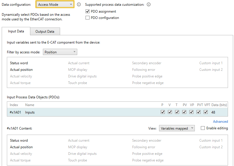
- Access Mode: You can select different PDO combinations for different Access Mode.
- Criteria for choosing this type:
- The device should support PDO assignment, but not support PDO configuration.
- The device should be a drive (I/O is not supported).
- Setup steps:
- Select Access Mode from the Data configuration drop-down menu, the tool will automatically detect and display the supported PDOs and the corresponding variables (PDO entries) of the device in the Input Data and Output Data fields.
- If you want to select the PDOs, in the Input Process Data Objects or Output Process Data Objects field, check the desired PDOs for each of the Access Mode (P, V, T, PV, VP, PVT, VPT).
- Criteria for choosing this type:
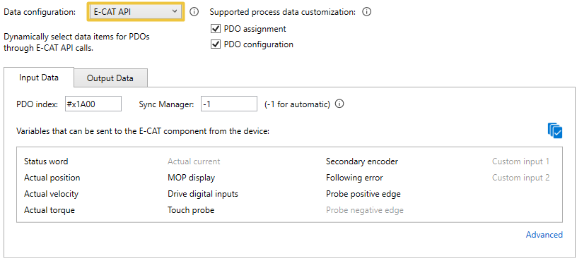
- E-CAT API: You can use the E-CAT API calls to automatically select the variables (PDO entries) for process data exchange.
- Criteria for choosing this type:
- The device should support the PDO configuration.
- The device should be a drive (I/O is not supported).
- Setup steps:
- Select E-CAT API from the Data configuration drop-down menu, the tool will automatically recognize the available variables (PDO entries) of the device and display them in the Input Data and Output Data fields.
- Edit the variables using the following E-CAT APIs:
- SetAxisAccessMode: Select one of the Access Mode, and the E-CAT component will automatically select the corresponding variables (PDO entries). The E-CAT component will decide whether to add the target position/velocity/torque and the actual position/velocity/torque variables to process data exchange according to the Access Mode you choose. Note that the associated McControlMode can only be used if the device supports the variables required for the selected Access Mode.
- Axis variable: In addition to E-CAT component automatically selecting the corresponding variables for each Access Mode, you can also add the required variables to the process data exchange using the Axis variable APIs. Ensure the required variables are supported by the device.
For .NET Class, please refer to ISubsystem properties (e.g. ActualCurrent, ActualVelocity).
- Criteria for choosing this type:
Note: Generally, when the Default mode is selected, there is no need to edit the variables unless the default variables are incorrect. To edit the variables, check the Enable editing box. To add more variables, use the
Add icon. To delete a variable, use the Delete icon. To edit a variable, use the Edit icon. To adjust the order, use the Move up or Move down icons.Note: If your devices support PDO assignment, then you can select the PDOs. If your devices support PDO configuration, then you can edit the variables. For more details about how to set up PDOs in Manual mode, see Customize PDOs for Devices.
Note: Generally, there is no need, and it is not allowed to edit the variables unless the variables are incorrect. To edit the variables, check the Enable editing box and select a PDO. The corresponding variables will be displayed in the below area. To add more variables, use the
Add icon. To delete a variable, use the Delete icon. To edit a variable, use the Edit icon. To adjust the order, use the Move up or Move down icons.Note: Generally, there is no need, and it is not allowed to edit the variables unless the variables are incorrect. To edit the variables, check the Enable editing box and select a PDO. The corresponding variables will be displayed in the below area. To add more variables, use the
Add icon. To delete a variable, use the Delete icon. To edit a variable, use the Edit icon. To adjust the order, use the Move up or Move down icons.
Descriptions of the variables supported by E-CAT component for process data exchange
The E-CAT ESI Import Tool can automatically detect a device's supported PDOs and the corresponding variables (PDO entries), and display variables in the Input Data and Output Data fields.
- Status word: The device status, which can be one of the following: not ready to switch on, switch on disabled, ready to switch on, switched on, operation enabled, quick stop active, fault reaction active, and fault.
- Actual position: The actual position.
- Actual velocity: The actual velocity.
- Actual torque: The actual torque.
- Actual current: The actual current.
- MOP display: The value of the modes of operation display variable. The operation mode could be CSP (Cyclic Synchronous Position), CSV (Cyclic Synchronous Velocity), CST (Cyclic Synchronous Torque), etc.
- Drive digital inputs: The digital input of a drive.
- Touch probe: The touch probe status of a drive.
- Secondary encoder: The position from the secondary encoder if there are two encoders.
- Following error: The following error.
- Probe positive edge: The latched position value after a rising edge of the touch probe.
- Probe negative edge: The latched position value after a falling edge of the touch probe.
- Custom input 1: A user-defined object. This object must exist in the device's object dictionary.
- Custom input 2: A user-defined object. This object must exist in the device's object dictionary.

- Control word: This object is used to set the mode of the drive, which can be read by status word.
- Target position: The commanded position.
- Target velocity: The commanded velocity.
- Target torque: The commanded torque.
- Torque offset: The torque's offset used in torque mode.
- Modes of operation: This object is used to set the operation mode of the drive, which can be read by MOP display.
- Drive digital outputs: The digital output of the drive.
- Touch probe: Sends the touch probe command.
- Max torque: The maximum torque.
- Max current: The maximum current.
- Profile velocity: The Profile Velocity.
- Profile acceleration: The Profile Acceleration.
- Profile deceleration: The Profile Deceleration.
- Homing method: The homing method.
- Custom output 1: A user-defined object. This object must exist in the device's object dictionary.
- Custom output 2: A user-defined object. This object must exist in the device's object dictionary.
Dependency table between functions/APIs and variables
The table below shows the variables that the functions or APIs will rely on.
| Functions / APIs | Required process data variables |
|---|---|
|
Direct Position control mode, Master Interpolation Position control mode, |
Target position |
|
Direct Velocity control mode, PID Velocity control mode, Master Interpolation Velocity control mode, RtecatSetAxisVelocity, |
Target velocity |
|
Direct Torque control mode, PID Torque control mode, Master Interpolation Torque control mode, RtecatSetAxisTorque, RtecatGetAxisTorque, |
Target torque Actual torque |
|
Control mode switching while powered on, |
MOP display Modes of operation |
|
Touch probe, |
Touch probe (input: status) Touch probe (output: control) Probe positive edge Probe negative edge |
|
RtecatGetAxisDigitalInput |
Drive digital inputs |
|
RtecatWriteAxisDigitalOutputs, RtecatGetAxisDigitalOutput, RtecatSetAxisDigitalOutput |
Drive digital outputs |
|
Actual current |
|
|
Actual torque |
|
|
Actual velocity |
|
|
RtecatSetAxisEncoder |
Second encoder |
|
Following error |
|
|
RtecatGetAxisTorqueOffset, RtecatSetAxisTorqueOffset |
Torque offset |
|
Maximum torque |
|
|
Maximum current |
|
|
Profile velocity |
|
|
Profile acceleration |
|
|
Profile deceleration |
Related topics: