This section provides information about the E-CAT Configuration Tool user interface.
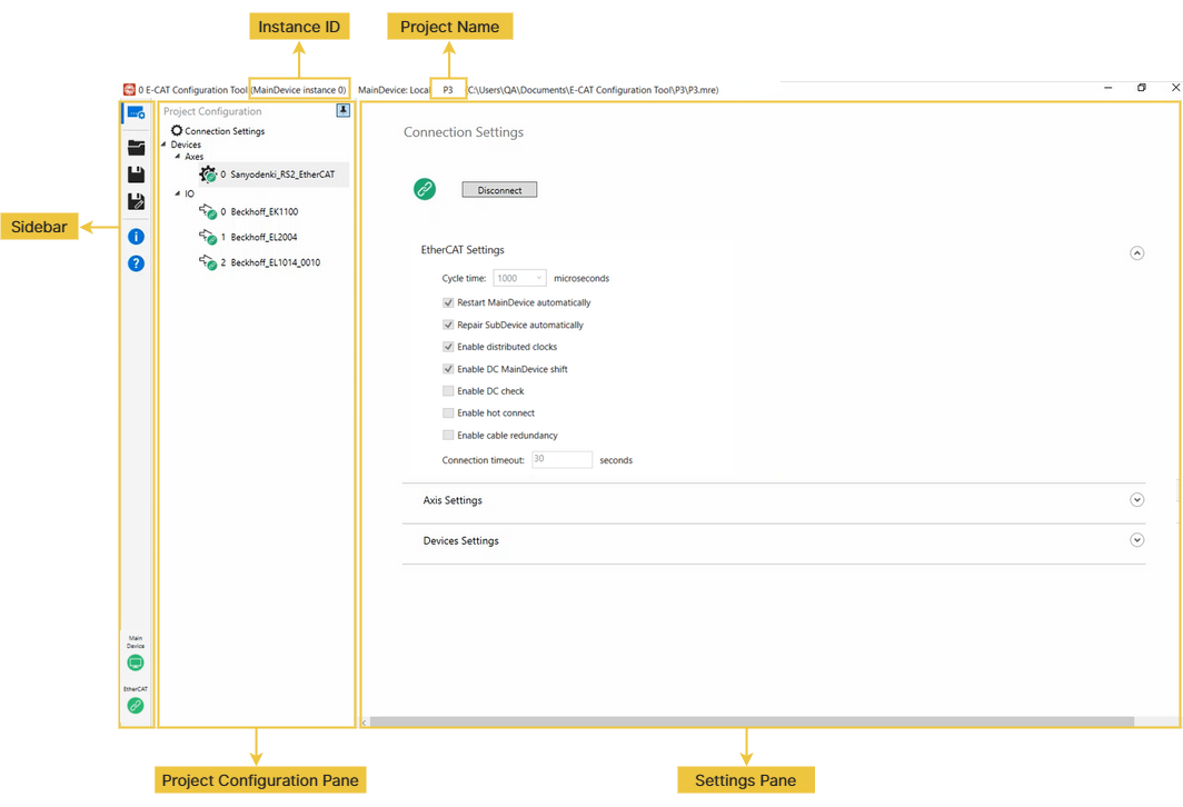
Instance ID
You must create at least one E-CAT MainDevice instance before using the wRTOS E-CAT Configuration tool.
If you select an E-CAT MainDevice instance ID when connecting to the E-CAT MainDevice, the ID is displayed. See Step 3 in Using wRTOS E-CAT Configuration Tool.
Project Name
When you create a new project, its name is displayed. See Step 4 in Using wRTOS E-CAT Configuration Tool. If you load a project file, its name and path are displayed.
Sidebar
Function icons on the Sidebar:
| Icon | Name | Action |
|---|---|---|
|
|
Project Configuration |
Select this icon to display the Project Configuration Pane. Within this pane, you can configure the MainDevice connection or device settings. See Project Configuration Pane for more details. |
|
|
Open (Startup Page) |
Select this icon to display the Startup page to create or open a project file. |
|
|
Save |
Select this icon to save the current settings to a folder. |
|
|
Save as |
Select this icon to save the current settings to a new folder. |
|
|
About |
Select this icon to display the tool information. |
|
|
Help |
Select this icon to display the tool's offline Help. |
|
|
MainDevice |
Select this icon to connect to or disconnect from the E-CAT MainDevice. Icon Status:
|
|
|
EtherCAT |
Select this icon to connect to or disconnect from the EtherCAT devices. Use it only when the MainDevice connection is established. Icon Status:
|
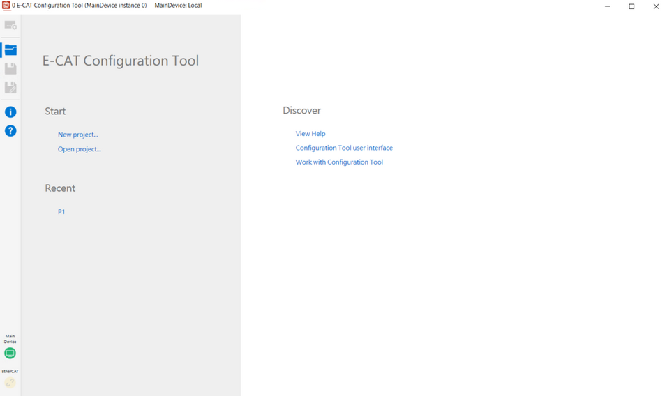
Startup Page
You can create or open a project file by selecting New project or Open project in the Start field. To create a new project, see Step 4 in Using wRTOS E-CAT Configuration Tool. The Recent field displays recently opened files. You can select a specific topic of this tool in the Discover field to access offline help.
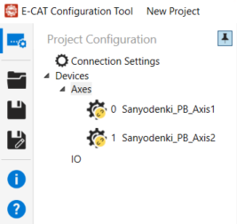
Project Configuration Pane
The Project Configuration Pane lists all project settings, including connection, axis, and I/O device settings. It allows you to perform several functions. Click the Pin button in the upper-right corner to pin or unpin this pane.
Device Icon Status
The device icons indicate the device's EtherCAT state.
![]()
- Green: The device is in the Op state.
- Yellow: The device is in the Offline state.
- Purple: The device is in the Init, PreOp, SafeOp, or Boot state.
Context Menu Functions
Right-click a device to open its context menu. The available functions depend on the device's EtherCAT state.
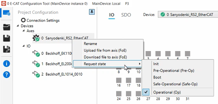
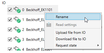
The left image shows the context menu for an axis, while the right image shows the context menu for an I/O.
- Rename: Changes a device's name. The names must follow the C++ naming convention.
- Upload file from axis/IO (FoE): Uploads a file from the device to your computer through File Access over EtherCAT (FoE). This option appears only when the device is in the Op or Boot state. If your device supports FoE, you can use it in the Boot state.
- Download file to axis/IO (FoE): Downloads a file from your computer to the device through File Access over EtherCAT (FoE). This option appears only when the device is in the Op or Boot state. If your device supports FoE, you can use it in the Boot state.
- Request state: Requests a change to a different EtherCAT state. For example, if the current state is Op and the requested state is PreOp, the tool changes the device's state as follows: Op → SafeOp → PreOp. Similarly, if the current state is Init and the requested state is Op, the tool changes the device state as follows: Init → PreOp → SafeOp → Op.
- Delete: Removes this device from the list. This option appears only when the device is offline.
- Read settings: Reads values from your device. This option is only available when the device is in the Op state.
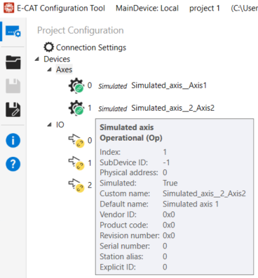
Tooltip
You can move your mouse pointer over a device to show its basic information.
Note: If the device is not scanned from the EtherCAT connection or added from database, the Station alias and Explicit ID will display as 0 (zero).
Note: The default value of Simulated is False when devices are added manually. Once connected to a simulated device, the value changes to True.
Adding Devices
To add an axis or I/O device:
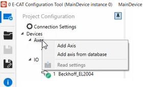
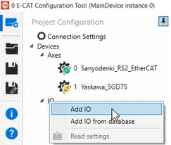
- Right-click Axes or IO to display the context menu:
- Add Axis/IO: Select this option to manually add an axis or I/O.
- Add axis/IO from database: Select this option to add an axis or I/O from the database. In this example, we add an axis from the database:
- Select a device in the Select Axis From Database dialog.
- Click OK to add the axis to the list.
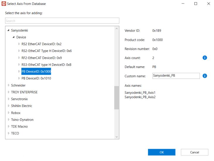
Note: For multi-channel drives, the Axis count field shows the number of axes, and the Axis names field automatically lists them in the format Drive name + Axis number.
Note: For multi-channel drives, this adds all its axes.
- Modify the connection parameters:
- Go to the Connection Settings page and select the Disconnect button to disconnect the EtherCAT connection.
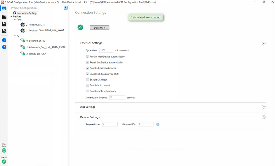
- In the Devices Settings field, enter the required axis/IO count. If you want to add simulated devices, enter a device value in this section. For example, if you already have one physical axis and three physical I/Os and want to add one simulated axis, enter 2 for the axis count.
- Select the Connection button. One simulated axis is created. Simulated hardware names are prefixed with Simulated.
Settings Pane
After selecting Connection Settings or a device from the Devices list in the Project Configuration Pane, its data will be displayed in this pane.
Connection Settings
The Connection Settings page appears when you select Connection Settings in the Project Configuration Pane. This page contains the basic EtherCAT and device settings you must configure before connecting to the E-CAT MainDevice.
Connect Button
You can select this icon to connect to or disconnect from the EtherCAT devices. This button functions like the EtherCAT icon in the bottom-left corner of the Sidebar. Since these devices are connected to the E-CAT MainDevice, use this button only when the MainDevice connection is established.

Icon Status:
- Green: When the icon turns green, it indicates that the connection is established within this tool or started by other applications.
- Purple: When the icon turns purple, it indicates that the MainDevice is in the Init, PreOP, or SafeOP state rather than the OP state.
- Yellow: When the icon turns yellow, the connection is disconnected.
Note: All settings are preserved if the tool is not closed, even if you select the Disconnect button.
Note: When an EtherCAT connection is established, the tool checks whether the connected devices match those from the selected project. If they do not match, the tool initiates the Device Matching process.
EtherCAT Settings
You can configure EtherCAT connection properties in this section.
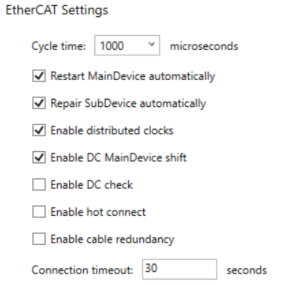
- Cycle time: Select an EtherCAT network cycle time from the drop-down list or enter a value in the box. The fastest cycle time supported by the wRTOS Fieldbus license is 1 millisecond (1,000 microseconds). The wRTOS E-CAT High Speed Timer license requires a faster cycle time below 1,000 microseconds.
Note: The cycle time must be a multiple of the wRTOS HAL Timer Period. If it's not, an error message will be displayed, and the MainDevice will not start. To set up the HAL timer period, see HAL Timer Period in wRTOS Settings.
- Restart MainDevice automatically: If a cable is disconnected, the MainDevice will restart automatically once the cable is plugged back in.
- Repair SubDevice automatically: If any SubDevice disappears due to the replacement of a servo drive, cable disconnection, power cut, or other issues, or if it encounters an EtherCAT error state, it will restart automatically. SubDevices that are not in an error state remain unaffected and continue to function normally.
- Enable distributed clocks: Select this option to enable or disable distributed clock synchronization.
- Enable DC MainDevice shift: Select this option to enable DC MainDevice shift mode, allowing the reference clock to synchronize devices on the EtherCAT network.
- Enable DC check: Select this option to enable distributed clock (DC) verification during MainDevice startup.
- Enable hot connect: Select this option to allow new hardware to be added to an EtherCAT network while the MainDevice is running. The wRTOS E-CAT Hot Connect license is required to use this function.
- Enable cable redundancy: Select this option to enable cable redundancy. The last SubDevice is connected to another network interface card on the computer, ensuring that all SubDevices remain communicable even if one cable is broken. The wRTOS E-CAT Cable Redundancy license is required to use this function.
- Connection timeout: The time allotted for hardware to connect to the MainDevice. An error message will appear if a connection is not established within the given time. Some hardware may require more than 30 seconds to establish a connection.
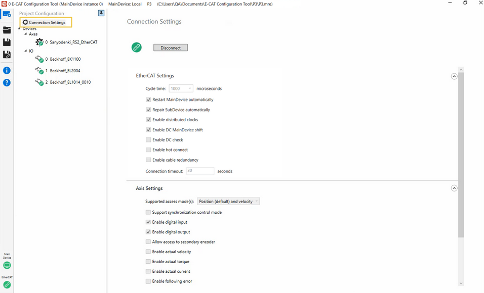
Axis Settings
You can configure data transfer between the E-CAT MainDevice and axes (SubDevices). Note that if a SubDevice does not support the selected data transmission, the transmission will not occur. You can use E-CAT ESI Import Tool to check the device's ESI data.
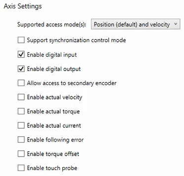
- Supported access mode(s): Select a data transfer mode for EtherCAT drives.
- Position: In this mode, position commands are sent to the drives. Available control modes include modeDirectPos, modeMasterIntPos (default), and modeSlaveInt.
- Velocity: In this mode, velocity commands are sent to the drives. Available control modes include modeDirectVel, modeMasterIntVel (default), and modePidVel.
- Torque: In this mode, torque commands are sent to the drives. Available control modes include modeDirectTor, modeMasterIntTor (default), and modePidTor.
- Position (default) and velocity: In this mode, drives use position commands by default but can be switched to velocity commands. Available control modes include modeDirectPos, modeMasterIntPos (default), modeSlaveInt, modeDirectVel, modeMasterIntVel, and modePidVel.
- Velocity (default) and position: In this mode, drives use velocity commands by default but can be switched to position commands. Available control modes include modeDirectPos, modeMasterIntPos, modeSlaveInt, modeDirectVel, modeMasterIntVel (default), and modePidVel.
- Position (default), velocity and torque: In this mode, drives use position commands by default but can be switched to velocity or torque commands. Available control modes include modeDirectPos, modeMasterIntPos (default), modeSlaveInt, modeDirectVel, modeMasterIntVel, modePidVel, modeDirectTor, modeMasterIntTor, and modePidTor.
- Velocity (default), position and torque: In this mode, drives use velocity commands by default but can be switched to position or torque commands. Available control modes include modeDirectVel, modeMasterIntVel (default), modePidVel, modeDirectPos, modeMasterIntPos, modeSlaveInt, modeDirectTor, modeMasterIntTor, and modePidTor.
- Support synchronization control mode: Select this option to enable the Modes of Operation and Modes of Operation Display objects. It changes the control mode through PDO instead of SDO, allowing faster mode changes (usually within 3-5 cycles). Not all servo drives support this feature.
- Enable digital input: Select this option to enable access to digital inputs for all axes. Note that not all axes have digital inputs.
- Enable digital output: Select this option to enable access to digital outputs for all axes. Note that not all axes have digital outputs.
- Allow access to secondary encoder: Select this option to enable access to an axis's internal position.
- Enable actual velocity: Select this option to add the actual velocity variable to PDO.
- Enable actual torque: Select this option to add the actual torque variable to PDO.
- Enable actual current: Select this option to add the actual current variable to PDO.
- Enable following error: Select this option to add the following error variable to PDO.
- Enable torque offset: Select this option to add the torque offset variable to PDO.
- Enable touch probe: Select this option to add the touch probe control and status variables to PDO.
Devices Settings
You can configure the number of devices to use. If physical devices are connected, you can leave this value as zero. If no physical devices are available, enter values in the Required axes and Required IOs fields to create simulated devices. See Adding Devices for more details.
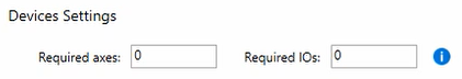
- Required axes: Specifies the number of axes to be created on the EtherCAT network. If the value exceeds the number of physical axes, the tool creates simulated ones to meet the requirement. For example, if the value is 5 and there are 3 physical axes, 2 simulated axes will be created.
- Required IOs: Specifies the number of I/Os to be created on the EtherCAT network. If the value exceeds the number of physical I/Os, the tool creates simulated ones to meet the requirement. For example, if the value is 4 and only 1 physical I/O is available, 3 simulated I/Os will be created.
Device Settings
The Device Settings page appears when you select a device from the Project Configuration Pane. The IO page allows you to read devices' I/O data or write data to the device output. The SDO page provides access to the devices' Service Data Object (SDO).
Note: If other applications establish the EtherCAT connection instead of this tool, you can use the tool to observe and manipulate real-time I/O signals and parameters for debugging and troubleshooting. After running your application, open E-CAT Configuration Tool to view these signals.
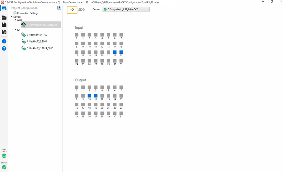
IO Page: Axis device
Choose an axis device and select the IO tab to access this page. This page allows you to read device input and output data or write data to the device output. Gray squares indicate a FALSE input/output, while blue squares indicate TRUE. To change an output value, click a square in the Output field to toggle between TRUE and FALSE.
Note: This page appears only when the selected device's EtherCAT state is in the Op state.
IO Page: I/O device
Choose an I/O device and select the IO tab to access this page. This page displays the device's Process Data Object (PDO) variable list, which may include inputs, outputs, or both, depending on the device's capabilities. The variable definitions are retrieved from the ESI file.
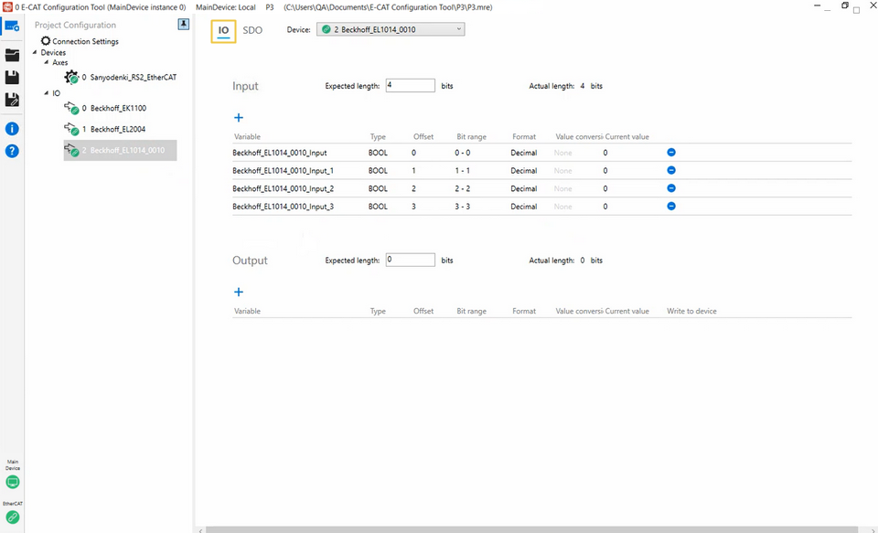
The above image illustrates the IO page when the selected I/O device supports only input.
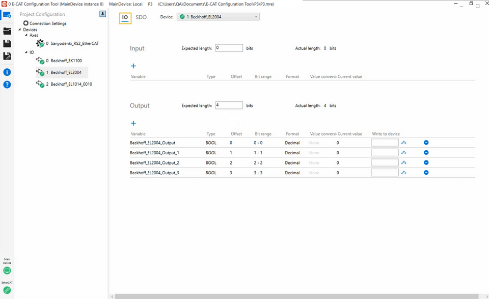
The above image illustrates the IO page when the selected I/O device supports only output.
- Expected length: Enter the expected length of the input or output.
- Actual length: Displays the full length of the input or output.
- Variable: Displays the variables of the input or output. You can edit them by double-clicking the column.
- Type: Displays the data type of variables. You can edit them by double-clicking the column. Available types include Boolean, Single, Double, Int8, Int16, Int24, Int32, Int64, UInt8, UInt16, UInt24, UInt32, and UInt64.
- Offset: You can specify the offset to the location to be read or written by double-clicking the column. When the data type is Boolean, the offset unit is a bit. Otherwise, the offset unit is a byte.
- Bit range: Displays the bit range.
- Format: The format of the value read from or written to the device, either Decimal or Hexadecimal. You can edit them by double-clicking the column.
- Value conversion: This option is for analog I/O device users who want to see a decimal value instead of hexadecimal. The default setting is None. Click None to display the Value Conversion dialog to convert a value. After conversion, None will change to Enabled. Note that a Boolean value can't be converted.
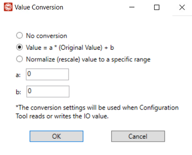
Options in the Value Conversion dialog:- No conversion: When this option is selected, the entered value is not converted. Current value shows the value you write.
- Value = a * (Original Value) + b: Select this option to apply the equation when converting values. After selecting it, entering a value in the Write to device box and clicking
 will apply the equation to compute the Current value. For example, if you enter 20 and click , the Current value will display 20; entering 21 and clicking will display 21.
To use the equation, assign values to a and b, and the tool will compute the Original Value based on the entered value. For example, if you set a to 0.01 and b to 20, entering 21 in the Write to device box and clicking results in the equation:
21 = 0.01 * Original Value + 20
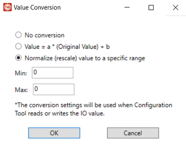
Solving for Original Value gives 100. When you switch to No conversion without changing the entered value (21), the Current value will display 100. - Normalize (rescale) value to a specific range: Select this option to define a range for controlling your machine. For example, if you want to control a voltage range between 0 V and 10 V, set Min to 0 and Max to 10. If you use an I/O device with a UInt16 data type, you can enter a value between 0 and 65535 to correspond to the 0 V – 10 V range.
- Current value: Displays the current value. You can edit it by entering a value in the Write to device box and click the Write icon. The value is only available when the device is in the OP state.
- Write to device: Enter a value and select the Write icon to write it to the variable. This function is only available when the device is in the OP state.
- Add button
 : Select this button to add a new variable to the input or output. If the input or output can't accept the variable, the Bit range and Current value will be displayed in red.
 - Delete button
 : Select this button to delete the variable. If you accidentally delete the variable and want to restore it, follow these steps:
- On the Connection Settings page, click Disconnect.
- Exit wRTOS E-CAT Configuration Tool.
- When prompted to save the current project, select NO.
- When prompted to shut down the wRTOS Subsystem, select YES or NO.
- Restart wRTOS E-CAT Configuration Tool.
- Open a project saved before you delete the variable or create a new project.
- Connect the E-CAT MainDevice to the same hardware.
- All the I/O variables will be restored to their default settings.
SDO Page
Choose an axis or I/O device and select the SDO tab to access this page. This page provides access to the devices' Service Data Object (SDO). You can configure object values or add objects to the Device Initialization Commands field for execution when the EtherCAT connection is established. The settings on this page are the same for axis and I/O devices.
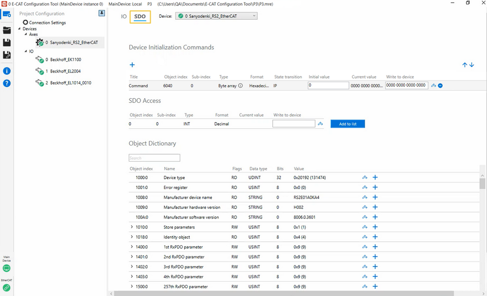
Device Initialization Commands
The initial SDO commands run every time the hardware connects to the MainDevice. You can add SDO objects to this area.
- Title: The object name.
- Object index: The object index.
- Sub-index: The entry's index.
- Type: The object's data type. Available types include STRING, Byte array, USINT, SINT, UINT, INT, UDINT, DINT, REAL, and LREAL. If you select Byte array, follow these guidelines to enter the value:
- Decimal format: Enter a series of space-separated numbers. For example: 125 3 20 5
- Hexadecimal format: Each byte is represented by two hexadecimal characters. For example: 7D031405. Spaces between bytes are optional, as shown here: 7D 03 14 05 or 7D03 1405
- Format: The value format, either Decimal or Hexadecimal, read from or written to the object.
- State transition: Specifies the EtherCAT transition state when a command is sent during the transition process. Three transition states are specified: IP, PS, and SO.
- IP: A command is sent after the device transitions from the Init state to the PreOP state, indicating that the sending occurs during the PreOP state.
- PS: A command is sent immediately before the device transitions from the PreOP state to the SafeOP state, indicating that the sending occurs during the PreOP state.
- SO: A command is sent immediately before the device transitions from the SafeOP state to the OP state, indicating that the sending occurs during the SafeOP state.
Note: EtherCAT states may change due to different connection methods. Here are two major scenarios:
Scenario A: If you use the wRTOS E-CAT Configuration Tool to establish an EtherCAT connection by clicking the Connect button on the Connection Settings page, all devices will transition to the OP state. Subsequently, if the tool detects discrepancies between the connected devices and those listed in the project file, the Device Matching process will be initiated. After completing the Device Matching process, the tool will revert the state of the devices to PreOP or SafeOP to send any necessary initialization commands. Once the commands are sent, all devices will transition back to the OP state.
Scenario B: If you use the E-CAT APIs to establish an EtherCAT connection with a Configuration Tool project file, the MainDevice will directly transition the devices from the Init state to the OP state and send the initialization commands during this transition. The Device Matching process will be omitted in this case.
- Initial value: The object's initial value. You can assign a specific value here if you want the device to use it every time it connects to the MainDevice.
- Current value: The object's current value. You can edit it by entering a value in the Write to device box and click the Write icon. The value is only available when the device is in the OP/Safe-Op/Pre-Op state.
- Write to device: Enter a value and select the Write icon to write it to the object. This function is only available when the device is in the OP/Safe-Op/Pre-Op state.
- Add button : Select this button to add an empty object. All columns are editable. Double-click the space or text in the field. After entering a value, press the Enter key.
- Delete button
 : Select this button to delete the command.
SDO Access
You can read and write the SDO objects not listed in the object dictionary. The firmware may contain these objects, which you can access here. This field is only available when the device is in the OP/Safe-Op/Pre-Op state. All columns are editable. Double-click the columns to edit the values.
- Object index: Enter an object index.
- Sub-index: The entry's index.
- Type: The object's data type. Available types include STRING, Byte array, USINT, SINT, UINT, INT, UDINT, DINT, REAL, and LREAL. You must know the correct type to read or write the value.
- Format: The value format, either Decimal or Hexadecimal, read from or written to the object.
- Current value: The object's current value. You can edit it by entering a value in the Write to device box and click the Write icon.
- Write to device: Enter a value and select the Write icon to write it to the object.
- Add to list: Select this button to add this item to the Device Initialization Commands field.
Object Dictionary
The object dictionary retrieved from an ESI file.
- Search box: Use the search box to quickly find an object. Type the object's index or name to filter the results. The search box can't find the object's entry (Sub-index).
- Object index: The object index.
- Name: The object name.
- Flags: The object's read and write permission.
- Data Type: The object's data type. Available types include STRING, Byte array, USINT, SINT, UINT, INT, UDINT, DINT, REAL, and LREAL. If you select Byte array, follow these guidelines to enter the value:
- Decimal format: Enter a series of space-separated numbers. For example: 125 3 20 5
- Hexadecimal format: Each byte is represented by two hexadecimal characters. For example: 7D031405. Spaces between bytes are optional, as shown here: 7D 03 14 05 or 7D03 1405
- Bits: The bit size of the device's data type.
- Value: The value read from or written to the device. A value that starts with 0x is hexadecimal, while the value in parenthesis is decimal.
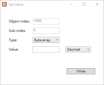
- Write button : Select this button to open the Set Value dialog and write the value to the object. When you select ASCII from the Type drop-down list, only ASCII characters can be entered in the Value box. When you select Binary, only hexadecimal values of up to 8 characters (4 bytes) can be entered in the Value box.
- Add button : Select this button to add this object to the Device Initialization Commands field.
Related topics: